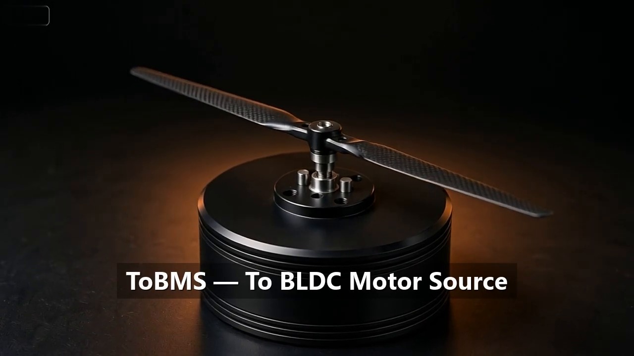
T-MOTOR has published a 46-second factory film that follows its drone motor manufacturing line from machined metal to assembled propulsion units. There is no narration, and no motor appears on screen by name. The clip is a montage of stations — a bank of CNC machining centres, a winding head laying copper wire onto a stator, solder-paste printing across a panel of ESC boards, a robotic press working along a conveyor — and its argument is carried entirely by what the camera shows: the steps behind a finished drone motor happen on automated equipment, inside the manufacturer’s own plant.
This article reconstructs the six stations visible in the film and explains what each one fixes in place in the finished product. Nothing here is attributed to the video beyond what its frames show.
What the Clip Shows
Published on the official T-MOTOR FOR UAV DRONE channel on October 23, 2026, the film runs for 46 seconds under the title “Amazing! Inside a Drone Motor Factory — How They Automated Their Production Line”. It opens on a motor bell rotating under inspection lighting, passes an engineering review around a meeting table and a CAD workstation showing circular motor drawings, and then settles onto the production floor: a row of CNC machining centres, a rotary press station, a winding machine laying copper into stator slots, solder-paste printing over a stencil onto a panel of ESC boards, the populated board panel under a test probe, and a robotic cell pressing components along a conveyor line.
Four short captions run across the film — that stable quality in industrial drone power comes from automated precision manufacturing, and that the manufacturer’s own factory strength speaks for itself. None of the captions carries a number, and no model appears by name: read carefully, the film is a process statement rather than a specification source, a manufacturer showing where the consistency of its drone motor manufacturing comes from.
Original Video
Source: T-MOTOR FOR UAV DRONE YouTube Channel
Video: Amazing! Inside a Drone Motor Factory — How They Automated Their Production Line
Six Stations on the Drone Motor Manufacturing Line
The frames in the film break into six stations. Together they cover the two halves of a propulsion system — the motor itself and the ESC that drives it — and each station exists because a property of the finished product is decided there, on a BLDC motor production line rather than at a bench afterwards.
Machining the bell, hub and shaft seats
The widest shot of the film is a row of CNC machining centres, followed later by a single milling operation cutting into an aluminium part under coolant. The rotating assembly of an outrunner — the bell that carries the magnets and the hub that carries the shaft — is where runout is set. If the bearing seats and the magnet seating surface are not concentric with the axis of rotation, the air gap varies as the rotor turns, and no downstream adjustment recovers it. Machining these features on automated equipment, in repeatable setups, is what keeps unit-to-unit variation small enough that the rest of the line can be built around it.
Winding the stator
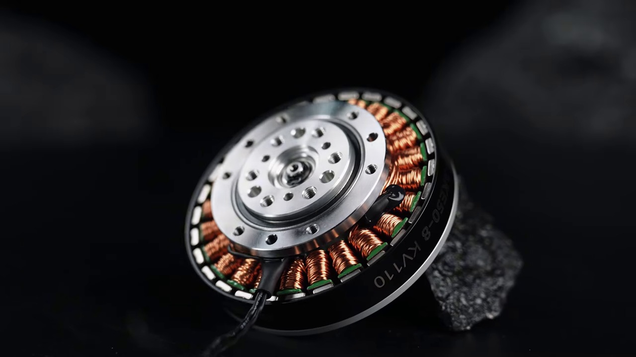
The clearest close-up in the film is a winding head laying copper wire into a stator. On a drone motor manufacturing line, winding is the station where two motors of the same model drift apart if the process drifts: turn count sets KV, wire tension and lay order set winding resistance and heat distribution, and a nicked or crossed wire is a latent failure rather than a visible one. Automating the operation does not change the physics, but it removes the hand-to-hand variation that manual winding introduces across a shift, which is exactly the spread the film’s captions argue against.
Building the rotor and bonding magnets
Later frames show a robotic arm and a press working over a conveyor line. In an outrunner motor this is where the magnet ring is assembled into the bell: bond line thickness, magnet spacing and cure conditions decide cogging torque, and an unbalanced rotor leaves vibration that the bearings and the airframe both pay for. The film shows the automation itself; the adhesive and the tolerances belong to the per-model documentation rather than to a 46-second clip.
SMT for the ESC boards
Two frames belong to electronics: solder paste printed through a stencil onto a panel of ESC boards, and the same panel later populated and under test. The ESC is half of the propulsion system, and paste printing is the station that decides much of what follows — paste volume consistency across a panel is what allows reflow, inspection and test to mean the same thing for every board on it. That both halves of a BLDC motor production line appear in the same film matches how T-MOTOR publishes its ranges: as complete propulsion systems rather than standalone motors.
Press-fit and automated assembly
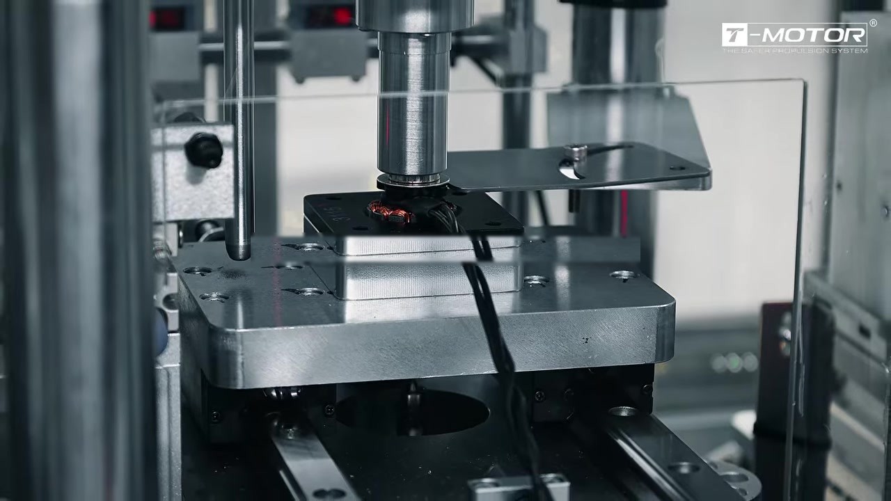
A rotary indexing table presses shafts into seated parts, with a station label marking the shaft press-in step, and the robotic cell repeats the pattern at line scale. Interference fits — shaft into hub, bearing into seat — are sensitive to force, alignment and surface condition, and they are the kind of operation that automation holds steady where a manual press drifts with fatigue. The film gives this station sustained screen time, which fits a clip whose subject is repeatability.
Inspection and engineering review
The film frames its narrative outside the production floor as well: a motor bell under ring lighting at the start, an engineering review around a whiteboard and a CAD workstation showing motor drawings in the middle. The inspection frame is the gate that the previous stations feed into; the review frames are the loop that feeds test information back into design. Neither carries measurable content, but both belong in a film about how a drone motor manufacturing process stays controlled.
Station by Station
Read as a sequence, the six stations are a working definition of drone motor manufacturing: metal is cut, copper is wound, the rotor is built, the electronics are printed and pressed, and every unit passes the same gate. The table below maps each station visible in the film to the property it controls.
| Station | What the frame shows | What it fixes in place | Why it matters at batch scale |
|---|---|---|---|
| CNC machining | Row of machining centres; milling under coolant (0:16, 0:38) | Bearing-seat and magnet-surface concentricity; runout | Air gap and vibration behaviour repeat across units |
| Stator winding | Winding head laying copper into a stator (0:24) | Turn count, wire tension, lay order | KV spread and winding resistance stay inside spec |
| Rotor assembly | Robotic arm and press on a conveyor (0:41) | Bond line, magnet spacing, rotor balance | Cogging and vibration do not drift unit to unit |
| ESC SMT | Solder-paste printing; populated panel under probe (0:28, 0:34) | Paste volume consistency, joint quality | Every board on a panel tests to the same basis |
| Press-fit assembly | Rotary indexing press station (0:18) | Interference-fit force and alignment | Shaft and bearing fits hold without rework |
| Inspection and review | Bell under ring lighting; meeting and CAD frames (0:01, 0:08) | Acceptance gate; design feedback loop | Defects caught in-plant; process corrected at source |
Timestamps refer to the published clip; descriptions are limited to what the frames show. The film publishes no tolerances, test data or capacity figures for any station.
What the Video States
The official description attributes two statements to T-MOTOR: that the tour takes place inside the T-MOTOR factory, with an automated production line in action, and that T-MOTOR builds complete propulsion systems for commercial UAVs, with a wide range of thrust options for multirotor, fixed-wing and VTOL platforms. Both are quoted here as the manufacturer’s own statements. The film itself is a process showcase; the per-model specification pages remain the source for the figures that size an airframe.
Why Drone Motor Manufacturing Consistency Matters in Batch Programs
A single motor is judged by its own measurements. A fleet is judged by the spread between its motors, and in drone motor manufacturing that spread is set on the line, not on the test bench. Two properties follow. First, thrust and current draw that repeat across units let a flight controller be tuned once and trusted across the fleet — a motor that draws measurably more current than its siblings at the same command heats differently and ages differently. Second, rotor balance that repeats keeps vibration inside the envelope the sensors and the structure were designed for, which on camera gimbals and inspection payloads is a performance limit, not a comfort issue.
For procurement, the practical reading of a film like this one is direct. It is evidence that the manufacturer runs its own automated drone motor manufacturing line, which supports the expectation of batch consistency — one specification applying to every unit. The per-model figures held in the ToBMS product records complete the picture, pairing the process shown here with the numbers each airframe is sized around.
Frequently Asked Questions
What does drone motor manufacturing look like inside the T-MOTOR factory?
The published clip shows six stations: CNC machining of the bell and hub, automated stator winding, rotor and magnet assembly, solder-paste printing and testing for ESC boards, press-fit assembly on a rotary table, and inspection with an engineering review loop. It runs for 46 seconds and carries no narration.
Does the video publish any specifications?
No. The film and its description state that the production line is automated and that T-MOTOR builds complete propulsion systems for commercial UAVs, but they carry no tolerances, test data, capacity figures or model names. Sizing decisions should rest on the per-model specification pages.
Which platforms do the T-MOTOR propulsion systems cover?
Per the manufacturer’s own description, the propulsion systems built on this line cover multirotor, fixed-wing and VTOL platforms, with a wide range of thrust options across the ranges.
Why does winding consistency matter so much?
Turn count, wire tension and lay order decide KV, winding resistance and heat distribution — the figures a power train is sized around. Variation between motors in a fleet shows up as current-draw and temperature spread at the same command, which is why the winding station is automated in the film.
Explore on ToBMS
- Explore the UAV Motors category →
- Explore the Drone Motors category →
- Heavy-Lift Drone Motors: Three T-Motor Options from 2.85 kg to 101 kg Thrust →
- View the T-Motor manufacturer profile on ToBMS →
- More manufacturer films in the Video section →
About T-MOTOR
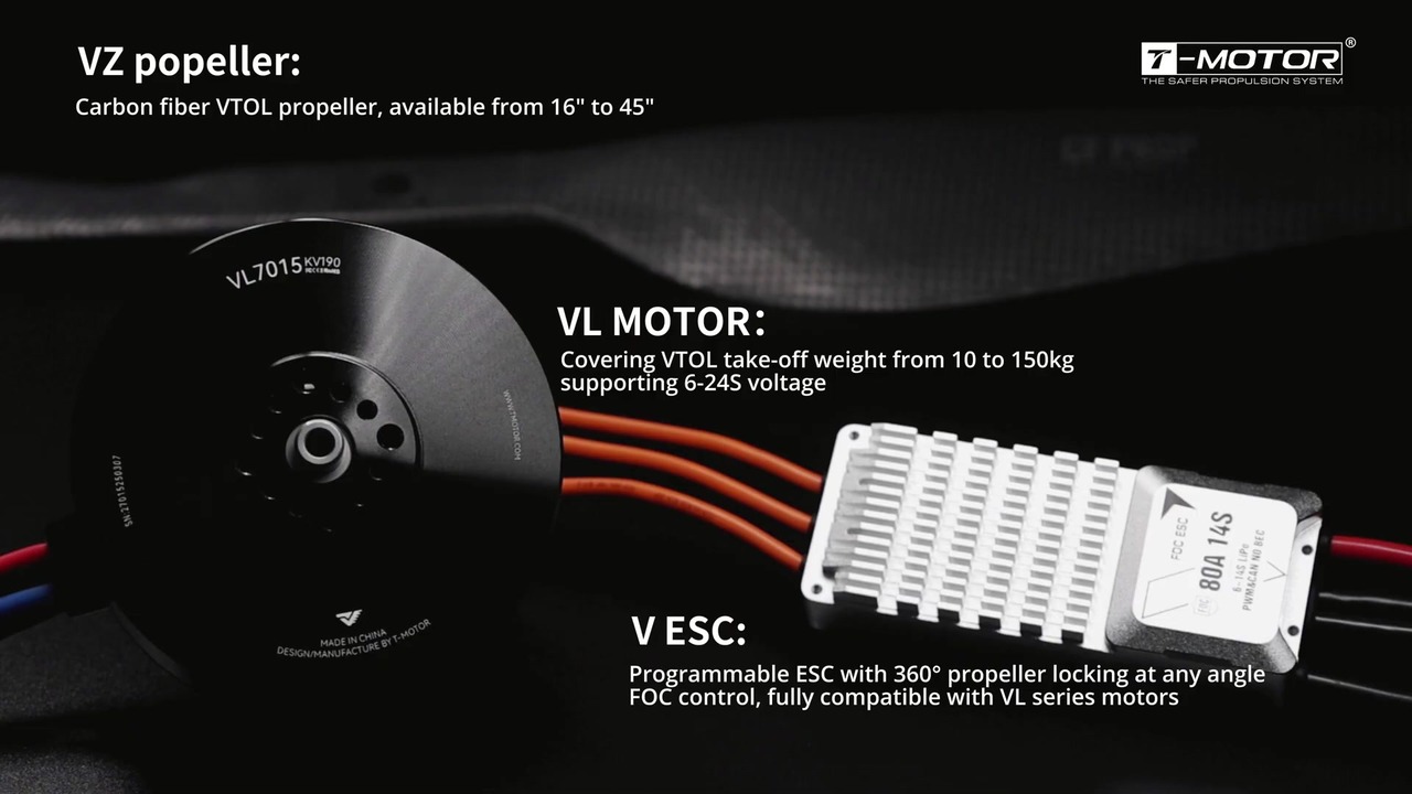
T-Motor develops brushless motors, ESCs and propellers for unmanned aircraft, with ranges covering multirotor, fixed-wing and VTOL platforms, and publishes matched motor, ESC and propeller sets rather than standalone motors. The film covered in this article is a tour of the T-MOTOR factory floor and of drone motor manufacturing at line scale, rather than a product demonstration — the counterpart to the range pages that carry the specifications.
Conclusion
A 46-second montage is not a specification source, and it does not try to be. What it documents is where the repeatability of T-MOTOR drone motor manufacturing comes from: six stations — machining, winding, rotor assembly, ESC electronics, press-fitting and inspection — run as an automated BLDC motor production line inside the manufacturer’s own plant. The figures that size an airframe stay where they belong, on the per-model pages; the film is the argument that those figures can be expected to hold across a batch, which is the quieter half of any procurement decision.