Cogging torque is the small, stubborn detent torque a BLDC motor produces even with no current applied — the magnetic attraction between rotor magnets and stator teeth that makes an unpowered shaft prefer certain angular positions. On a fast-spinning propeller motor the disturbance frequency climbs high enough that the driven system barely responds to it. On a camera gimbal, a direct-drive robot joint, or a pointing mechanism that creeps at a few degrees per second, it becomes the difference between smooth motion and a visible step. This guide explains where cogging torque comes from, which design choices suppress it, and how to judge it when the datasheet stays silent.
Quick Answer
Cogging torque is a position-dependent disturbance torque caused by the rotor magnets seeking minimum-reluctance positions against the slotted stator. It needs no current, it repeats many times per revolution, and it matters most near standstill, in slow continuous motion and through frequent low-speed reversals, where rotor inertia no longer smooths it away. A gimbal axis that visibly twitches at slow pan speed, or a robot joint that cannot hold a precise angle without dithering, is usually showing the detent rather than a controller fault.
Suppression is a motor-design problem before it is a control problem: fractional-slot winding layouts, skewed magnets or stator teeth, shaped magnet arcs and slotless constructions all attack the mechanism at its source, while higher pole counts can shift the detent disturbance to a higher spatial frequency in direct-drive designs. When a product page prints no figure — and most do not — the pole and slot data, a hand back-drive, and a low-speed current ripple test are the practical stand-ins for a number.
What Cogging Torque Is
Every slotted brushless motor carries this effect in some measure. Understanding cogging torque takes three ideas: why the rotor has preferred positions at all, why the disturbance fades with speed, and why it should not be confused with the broader family of torque ripple that appears only when the motor is driven.
Preferred magnetic positions
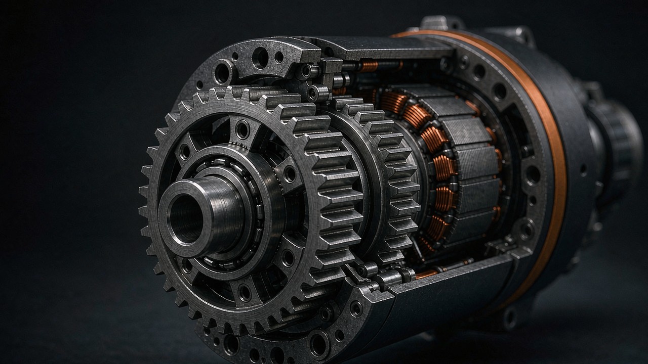
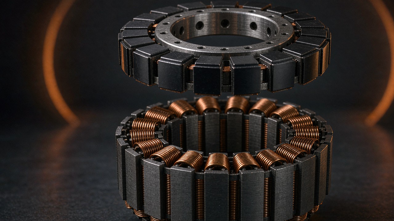
A permanent magnet rotor sitting next to an iron stator core is never magnetically neutral. The teeth of the stator concentrate the iron into discrete packages, and each rotor magnet is pulled toward the angular position where its flux path through the teeth offers the least reluctance. Between those positions the stored magnetic energy changes with angle, and the derivative of that energy with respect to angle is a torque — the cogging torque. Turn an unpowered slotted motor by hand and the detents felt at the shaft are exactly this energy landscape made tangible.
The number of detents per mechanical revolution is set by the geometry, not by the windings or the drive: it follows the least common multiple of the slot count and the pole count. A stator with 12 slots facing an 8-pole rotor produces 24 preferred positions per revolution, while a combination whose least common multiple is larger produces many more, individually weaker detents. That single arithmetic fact explains most of the design levers that come later — and why a detent problem is usually a slot and pole problem in disguise.
Why speed hides the detent
Cogging torque alternates sign as the rotor crosses each preferred position: it resists the motion on one side of the detent and assists it on the other, so over a full cycle its net work is zero. Zero net work does not mean zero motion disturbance, though. As speed rises the disturbance frequency climbs, and the rotor and load inertia act as a mechanical low-pass filter, so the resulting speed variation often shrinks below what the application notices. The effect itself does not vanish: the system simply stops responding to it, and how far that response falls depends on inertia, stiffness, damping and control bandwidth.
At crawl speed the filter disappears. A shaft turning a few degrees per second sits inside each detent long enough for the detent to show up directly as velocity ripple, position error, or a step the controller must fight. This is why the same motor class that works at 3000 rpm can struggle at 3 rpm, and why low-speed applications read motor pages differently from propulsion applications.
Cogging torque vs torque ripple
The two terms are related but not interchangeable, and mixing them up leads to wrong fixes. The detent torque exists with the motor unpowered; it is a pure magnet-versus-iron effect. Torque ripple is the broader term for any variation of output torque with rotor position while the motor is driven, and it sums several contributors: the detent component, the mismatch between the back-EMF waveform and the drive current waveform, commutation events in trapezoidal drives, and current-loop imperfections.
Two different objects of study sit inside those terms, and a short table keeps them apart. The distinction that matters for selection is which defects a drive can reach and which it cannot.
| Feature | Cogging Torque | Torque Ripple |
|---|---|---|
| Present with no current | Yes — a magnetic property of the iron and magnets | Usually described in driven operation |
| Main sources | Rotor magnets and stator slotting | Detent component, back-EMF harmonics, current waveform, commutation, control |
| Can drive tuning remove it | Not the underlying magnetic source | Some components can be reduced |
| Typical evaluation | Unpowered torque-versus-angle | Driven torque or motion measurement |
The practical distinction is that a drive can attack part of the torque ripple — sinusoidal FOC driving a sinusoidal back-EMF motor can reduce the commutation-related component — while the detent component rides through any drive unchanged, because it lives in the iron and magnets rather than in the current. CubeMars states the causal direction plainly on its gimbal motor pages: low cogging torque results in low torque ripple. The reverse is not true, which is why chasing ripple with drive tuning alone has a hard floor set by the motor hardware.
Where Cogging Torque Decides the Pick
Most motor selections never need to think about detent torque at all. Three application classes have no such luck, because their operating point sits exactly where the detent is strongest: at low speed, near standstill, or in slow reversal.
Camera gimbal axes
A stabilised camera axis spends its working life holding an angle against gravity and correcting disturbances of a few degrees. A detent torque strong enough to fight the correction appears in the footage as a tiny periodic oscillation, most visible in slow pans and static shots with long lenses. This is the application where low cogging torque is the explicit selling point rather than a hidden bonus, and the category guide Gimbal Motors: Low-KV Direct Drive for Stable Camera Platforms covers the class in selection terms — low KV windings, large hollow shafts, direct drive with no gearing anywhere in the axis.
The physics explains the pattern that guide observes: gimbal motors run high pole counts and direct drive partly because gearing changes the problem rather than solving it. In an ideal geared transmission, motor-side cogging torque is multiplied at the output by the reduction ratio, while the output-angle interval between detent events becomes smaller — the same detent then arrives more often in output terms. How much of it reaches the motion depends on the transmission stiffness, friction, backlash, damping and the control response. A gearbox therefore changes how the detent is transmitted and perceived; it does not simply eliminate the disturbance, and it does not automatically make the axis worse.
Direct-drive robot joints
A robot joint feels cogging torque in three places: in force control, where the disturbance masquerades as an external contact; in backdrivability, where the operator or the environment has to push through every detent by hand; and in position holding, where the servo loop dithers around a preferred magnetic position instead of settling on the commanded one. The resolution side of that settling problem — what the encoder can actually see — is covered in Encoder Resolution at a Robot Joint: Bits, Backlash, and Repeatability; the detent side decides how smooth the motion is between the encoder counts.
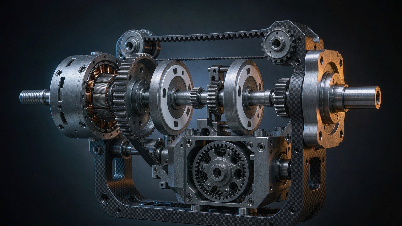
Quasi direct drive actuators accept a small ratio and live with the transparency; deep-ratio actuators bury the motor-side disturbance under multiplication but pay for it in reflected inertia and backlash. That trade is worked through in Reduction Ratio and Reflected Inertia: Sizing a Robot Joint Gearbox, and the low-ratio philosophy behind it in Quasi Direct Drive Actuators: What an 8:1 Ratio Buys You. Where the joint sits on that spectrum decides how much cogging torque matters at the output flange.
Precision pointing and tracking
Telescope mounts, LiDAR scanners, antenna trackers and pan-tilt payloads share the gimbal regime: slow, smooth, continuous motion where a periodic torque disturbance reads directly as pointing jitter — the visible end of torque ripple at a slow sweep. A tracker following a satellite pass or a scanner sweeping a scene cannot tolerate velocity ripple at the sweep frequency, and the frequency of the detent disturbance sits exactly in that band at working speed. In these mechanisms the datasheet rarely settles the question, because the row that would settle it is usually missing — the subject of a later section.
Design Levers That Reduce Cogging Torque
Cogging torque reduction is solved in the electromagnetic design, and the levers are well established. None of them is free: each one trades something — torque density, manufacturability, cost — for smoothness, which is why propulsion motors and gimbal motors end up looking so different.
Slot and pole combination
The first lever is the combination itself, and it sets periodicity rather than amplitude. The detent count per revolution follows the least common multiple of slots and poles, so a higher least common multiple means more frequent detent events; it does not automatically mean a weaker detent. The amplitude depends on the electromagnetic geometry — slot openings, magnet pole-arc ratio, air-gap distribution and harmonic cancellation. Fractional-slot windings, which use a non-integer number of slots per pole per phase, can help shape the spatial harmonic content and reduce cogging torque depending on the specific combination, and the result is a property of the complete electromagnetic design rather than of the winding classification alone.
The amplitude side matters as much as the count. Slot openings give the magnet flux a low-reluctance bridge, and narrower openings or closed-slot designs shrink the energy variation behind each detent, directly shrinking the detent amplitude. The trade is winding difficulty and leakage, so the opening width is a compromise the manufacturer makes once and the buyer inherits. Cogging torque reduction through slot-pole choice costs nothing in material; it is decided entirely on the drawing.
Skewing and magnet shaping
Skewing introduces an angular offset along the axial length of the machine: the detent positions at one end of the stack fall between those at the other end, and the resulting phase differences can reduce selected cogging torque harmonics through partial cancellation. Stepped skew — magnets assembled in axially offset segments — reaches a similar effect with easier manufacturing. The optimum skew angle depends on the slot-pole combination and the target harmonic, and the reduction trades against back-EMF shape, torque constant and manufacturing complexity to a degree set by the design.
Magnet shaping attacks the same harmonic content from the rotor side: arc profiles, pole-arc ratios, eccentric surfaces and chamfered edges all reshape the flux density distribution so its interaction with the slotting carries less energy at the detent frequencies. These measures are invisible on a datasheet but visible in the design intent wording — a page that states optimised electromagnetic design for smooth low-speed motion is usually reporting this family of cogging torque reduction work.
Slotless windings
The radical lever is to remove the teeth altogether. A slotless winding sits in a smooth air gap with no discrete iron packages, so there are no preferred positions and the mechanism behind the detent loses its foundation. Slotless motors can reach very low cogging torque because they remove the discrete stator teeth behind the main detent mechanism, but they are not automatically free of torque ripple: current waveform distortion, back-EMF harmonics, control errors and other electromagnetic effects can still produce it. They are a common option in instruments and medical devices where smoothness outranks everything. The cost is torque density: without teeth to concentrate flux, a slotless design needs more magnet material and more copper for the same torque, and the winding is harder to cool.
Between fully slotted and fully slotless sit the compromises — closed slots and magnetic wedges that present a smoother face to the air gap while keeping the teeth underneath. Cogging torque reduction in these designs is a matter of degree rather than elimination, judged case by case.
Pole-pair evidence from listed models
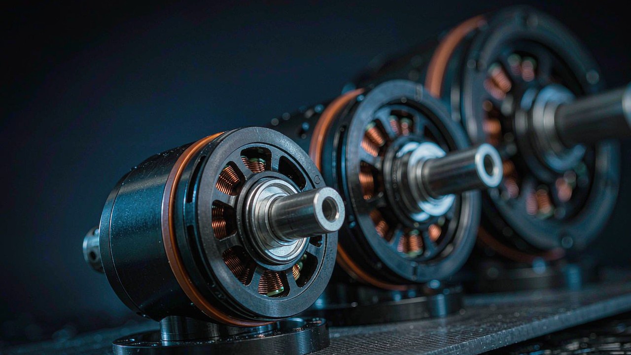
The gimbal and frameless families listed on this site show the levers in their published specifications. Within the CubeMars GL gimbal line, the pole-pair count climbs with frame size and payload class: 7 pole pairs on the 41 g GL30, 14 on the 230 g GL60, 20 on the 698 g GL100 that carries professional camera masses. The RI frameless inrunner line repeats the pattern on the robot-joint side: 7 pole pairs on the RI50, 8 on the RI80 V2.0, 14 on the RI100. Both families state low-cogging design intent on their product pages, and both pair that wording with pole counts far above the 3 to 4 pole pairs typical of a propulsion outrunner.
A higher pole-pair count can raise the spatial frequency of cogging torque, depending on the slot-pole combination. At a given shaft speed that shifts the disturbance to a higher frequency, where some mechanical systems attenuate the resulting motion ripple more effectively than others — inertia, stiffness, damping and control bandwidth decide how much. Pole-pair count alone does not establish low cogging torque amplitude; the amplitude belongs to the complete electromagnetic design and should be verified by measurement. The published counts remain useful as comparable structural information — a concrete row to read when the figure itself is not printed — not as a substitute for a measurement.
Cogging Torque: The Number That Rarely Appears on the Datasheet
Open the specification tables of the seven models compared later in this guide and a pattern emerges: six of them claim low detent behaviour in words and print no cogging torque figure, while the seventh, the GL60 II, prints a before-and-after pair. Rated torque, peak torque, resistance, inductance, inertia — all present on every page. The disturbance that decides low-speed smoothness is usually described only as a design intent.
Why manufacturers leave it blank
The omission is structural, not accidental. A detent figure needs a defined test rig — a low-speed constant-rotation drive, a torque sensor with millinewton-metre resolution, a controlled temperature — and no cross-vendor standard pins that rig down, so any printed number would be incomparable across brands and easy to challenge. The value also scatters with magnet tolerances and temperature, which makes a single printed figure a liability: the worst unit in a batch is the one the customer measures.
Marketing arithmetic pushes the same direction. The published figures are small next to rated torque — the GL60 II page that does state them prints 0.024 Nm dropping to approximately 0.015 Nm, a reduction it describes as 37.5%, on a motor rated at 0.6 Nm — and a small number beside a large one invites misreading. Words like low or ultra-low survive translation and comparison; a bare number does neither. The result is a specification culture in which the most important low-speed row is the detent row, and it is usually the one left blank.
Bench estimation without a dynamometer
The absence of a printed figure does not leave the bench empty-handed. Three checks need nothing beyond the motor, its drive, and patience. The first is the back-drive: rotate the unpowered shaft slowly by hand or with a light finger lever and feel for detents. A slotted motor with weak detents turns with a fine, even grain; a strong one clicks from position to position. The test is qualitative but instant, and it compares two candidate motors in minutes. It is a screening test rather than a measurement: bearing friction, seals, rotor alignment and any attached transmission colour the feel, so compare motors in the same configuration and, where possible, isolate the motor from gearbox and load.
The second check uses the drive as the instrument. Run the motor at a constant low speed under current control and watch the phase current on an oscilloscope or in the drive telemetry: at constant speed and constant load the current should be flat, and the detent disturbance shows up as a periodic current ripple at the detent frequency as the loop fights it. Current ripple here is a system-level diagnostic, not a quantitative substitute: its shape depends on control bandwidth, PWM strategy, back-EMF waveform, sensor accuracy and load disturbances as much as on the motor, so it shows how the drive responds to position-dependent disturbance rather than how large the detent is.
The third check is the step test at the application speed band. Command a slow constant-velocity move or a small position step and record actual velocity or position from the encoder; the periodic component of the velocity error is the fingerprint of the detent acting through the whole mechanics. This test measures the system rather than the motor alone — the disturbance as the mechanics actually deliver it — which is precisely its value for a selection decision. The three checks differ in what they can prove, and the hierarchy is worth keeping straight.
| Method | What it yields | Evidence level |
|---|---|---|
| Unpowered back-drive | Detent feel and character | Qualitative screening |
| Low-speed current ripple | Drive response to a periodic disturbance | Indirect diagnostic |
| Encoder velocity or position test | Actual system motion under load | System-level validation |
| Torque transducer, unpowered slow rotation | Torque-versus-angle waveform and amplitude | Direct measurement |
The last row is the one that produces a real figure, and it needs no dynamometer — only a torque sensor, a slow rotation and the motor completely unpowered.
What to ask the manufacturer
When the decision is expensive, the blank row becomes a question list. Ask for the measured peak and peak-to-peak cogging torque, the torque-versus-angle waveform behind those figures, whether the motor was completely unpowered during the test, the temperature, the angle resolution and the test method — and whether the numbers describe a single sample or batch statistics. A manufacturer that has done the cogging torque reduction work can usually answer all of it; silence on method is itself an answer, and figures from different vendors are only comparable when the conditions match. For the models carried on this site, the manufacturer pages and their downloadable documentation are the starting point, and the ToBMS product pages keep the published rows — pole pairs, torque, mass — comparable side by side.
How to evaluate cogging torque without a published datasheet value
- Read the slot-pole combination and any electromagnetic design information the page publishes.
- Run an unpowered back-drive as a qualitative screen between candidates.
- Use a torque transducer on a slowly rotating, unpowered shaft when a real waveform is required.
- Compare low-speed position or velocity ripple under identical operating conditions to judge the complete system.
Listed Models With a Stated Low-Cogging Design
The seven models below span the two classes where low-speed smoothness is the design brief: direct-drive gimbal motors and frameless inrunners for robot joints. All rows are as published on each manufacturer product page and were cross-checked against those pages in November 2026; the stated-intent column records the wording each page carries, and the data-availability column records whether a numeric figure accompanies it. These models are used as examples of published specification patterns, not as a ranking of low-cogging motors, and the same framework applies to products from other manufacturers. The table deliberately keeps to rows every page prints — torque, mass, pole count — so the comparison stays on auditable ground rather than on the qualitative wording alone.
| Model | Type | Rated Torque (Nm) | Peak Torque (Nm) | Pole Pairs | Weight (g) | Stated Design Intent | Numeric Cogging Torque Data |
|---|---|---|---|---|---|---|---|
| GL30 KV290 | Gimbal | 0.08 | 0.28 | 7 | 41 | Low cogging stated | Not published |
| GL60 KV25 | Gimbal | 0.6 | 1.75 | 14 | 230 | Low cogging stated | Not published |
| GL60 II KV28 | Gimbal with integrated driver | 0.6 | 1.5 | 28 | 276 | Ultra-low cogging stated | Published: 0.024 to 0.015 Nm |
| GL100 KV10 | Gimbal | 3 | 7.7 | 20 | 698 | Low cogging stated | Not published |
| RI50 KV100 | Frameless inrunner | 0.58 | 1.67 | 7 | 180.8 | Lower cogging stated | Not published |
| RI80 V2.0 KV75 | Frameless inrunner | 1.45 | 4.1 | 8 | 411 | Lower cogging stated | Not published |
| RI100 KV105 | Frameless inrunner | 1.76 | 4.95 | 14 | 500 | Ultra-low cogging stated | Not published |
Rows as published on each CubeMars product page, cross-checked November 2026. Only the GL60 II page prints a numeric figure — 0.024 Nm reduced to approximately 0.015 Nm, described on the page as a 37.5% reduction — and that row covers the 24 V variant. The pole-pair column and the stated-intent column are structural and qualitative information respectively, not measurements; the GL II sub-family carries an integrated driver board and a different winding layout, so its pole count does not line up with the GL rows around it.
The GL gimbal rows
The gimbal rows step up the payload ladder of a camera axis. CubeMars GL30 KV290 Gimbal Motor weighs 41 g and fits compact stabilisers; CubeMars GL60 KV25 Gimbal Motor holds 0.6 Nm continuously at 14 pole pairs for mid-size cameras; CubeMars GL60 II KV28 Gimbal Motor adds an integrated driver board with CAN and PWM interfaces, and it is the one page in this set that publishes a measured pair — 0.024 Nm reduced to approximately 0.015 Nm; CubeMars GL100 KV10 Gimbal Motor reaches 3 Nm of rated torque at 20 pole pairs for professional payloads. All of them are direct drive, with no gearbox between rotor and camera mass. The increasing pole-pair count across these models shows how electromagnetic configurations vary with payload class, but pole-pair count alone cannot establish which model has the lower detent, and the low-cogging statements stay qualitative design claims until comparable measurements exist.
The RI frameless trio
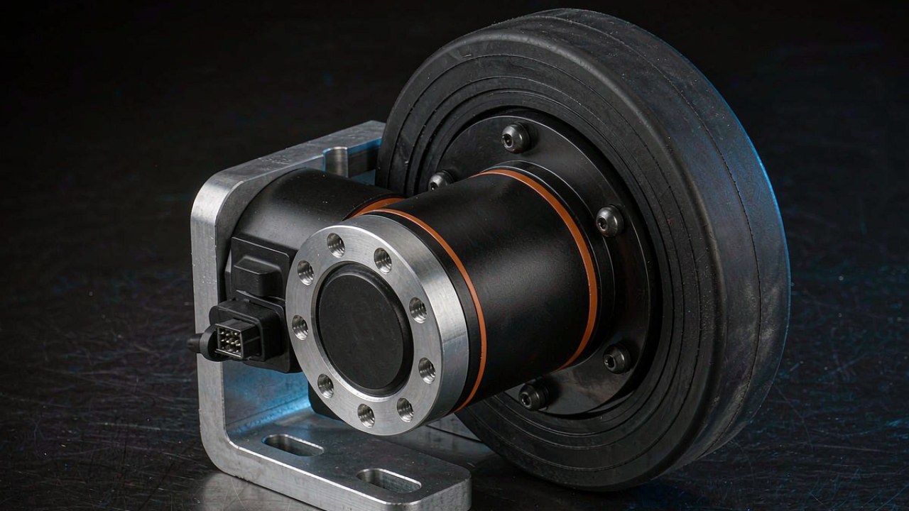
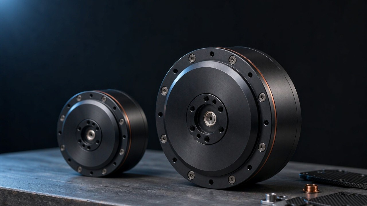
The frameless inrunners serve joints rather than cameras. CubeMars RI50 KV100 Frameless Inrunner Torque Motor at 180.8 g suits compact joints; CubeMars RI80 V2.0 KV75 Frameless Inrunner Torque Motor covers the mid range at 1.45 Nm rated; CubeMars RI100 KV105 Frameless Inrunner Torque Motor delivers 4.95 Nm of peak torque from 14 pole pairs, with its page stating ultra-low detent behaviour and fast response even at low speed. Frameless kits integrate into the joint structure itself — stator and rotor bolt into the housing — and the class selection logic is covered in Frameless Torque Motors: Choosing a Stator and Rotor Kit for Robot Joints.
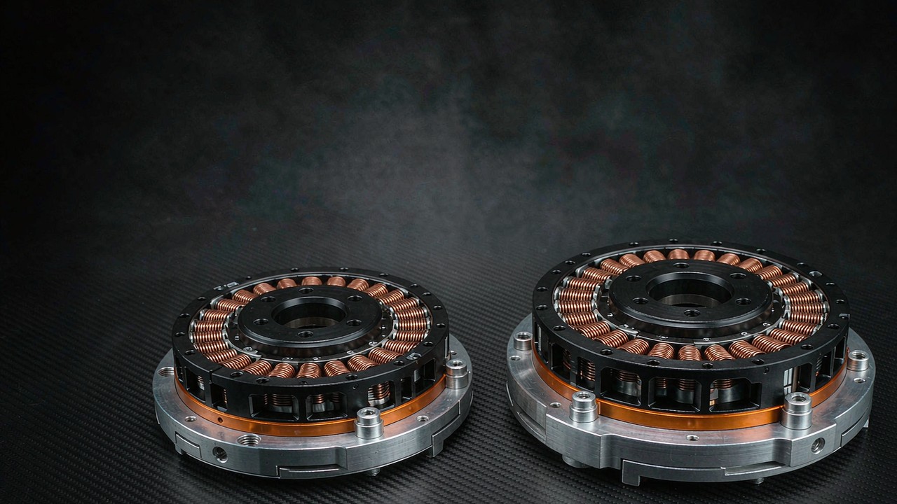
The official video above walks through the inrunner and outrunner frameless construction directly — the stator teeth, rotor magnets and winding layout that decide how much cogging torque a design produces — and shows the two architectures side by side on real hardware.
Choosing for Smooth Low-Speed Motion: A Checklist
The mechanism and the evidence assemble into an order of operations. Run it top to bottom when the application lives at low speed; skip it only when the operating point never leaves the regime where the detent is filtered away.
Step one: define the speed band
Write down the slowest useful motion and the holding duty before opening any product page. Near standstill, in slow continuous motion and in frequent low-speed reversals the detent behaviour of the motor is a first-order selection criterion — and there is no universal rpm threshold, because the impact depends on shaft speed together with rotor and load inertia, mechanical stiffness, damping, transmission ratio and control bandwidth. At high speed the disturbance frequency moves out of the mechanical response band, and the other rows matter more. An axis that both crawls and slews needs the crawl case to size the motor, because the fast case will take care of itself.
Step two: read the pole count and the layout
With no printed figure to compare, the structural rows carry the signal. More pole pairs, a fractional-slot winding, skewed magnets or teeth, and any stated low-cogging intent are the markers of design effort spent on smoothness; the comparison table above shows how those rows read in practice. Where the page is silent on structure, the manufacturer question list from the previous section applies — and cogging torque reduction claims without structural rows behind them deserve the skepticism that the blank-test-method note predicts.
Step three: budget the bench test
Plan to measure what the datasheet omits. The back-drive feel, the constant-speed current ripple and the low-speed velocity fingerprint each take under an hour with a drive and an encoder, and together they bracket the behaviour the printed rows cannot show. Sample two candidate motors if the budget allows: the comparison is more informative than either absolute reading, because the tests are relative by nature. A note on rig discipline: the same drive settings, the same speed and the same load condition must be used for both candidates, because current ripple amplitude depends on loop gains and speed as much as on the motor itself. A disciplined back-to-back comparison on one rig is worth more than two careful measurements on two different setups.
Step four: match the drive to the motor
The drive cannot remove the detent, but it decides how much of the wider torque ripple family survives to the output. Sinusoidal FOC paired with a sinusoidal back-EMF motor can suppress much of the commutation-related component; trapezoidal driving adds its own ripple on top. The magnetic floor — the detent — stays either way. The current and heating side of that pairing is covered in Continuous Torque vs Peak Torque: Duty Cycle, Thermal Limit, Torque-Speed Curve. Smoothness at the shaft is a motor property multiplied by a drive property, and the checklist closes only when both sides are chosen.
Key Takeaways
- Cogging torque is an unpowered, position-dependent detent torque from magnet-tooth attraction; it needs no current and repeats many times per revolution.
- Rotor and load inertia filter the disturbance at speed, so the detent decides selections only at low speed, near standstill, and in slow reversal.
- Cogging is one component of torque ripple — the component no drive tuning can remove, because it lives in the iron and magnets.
- Fractional-slot layouts, skewing, magnet shaping and slotless windings are the established design levers; slot-pole choice sets the periodicity, while the amplitude belongs to the complete electromagnetic design.
- Most datasheets print no figure, so cogging torque reduction is judged from pole-pair counts, stated design intent, a hand back-drive and a low-speed current ripple test.
Frequently asked questions
QWhat causes cogging torque in a brushless motor?
The attraction between the rotor permanent magnets and the discrete iron teeth of a slotted stator. Each magnet is pulled toward the angular position of lowest magnetic reluctance, and the change of stored magnetic energy with angle appears as a torque that alternately resists and assists rotation. The effect therefore needs no current — it is present even on an unpowered shaft — and its detent count per revolution follows the least common multiple of the slot and pole counts. In other words, the detent is the unpowered member of the torque ripple family.
QIs cogging torque the same as torque ripple?
No — cogging torque is one component of torque ripple, not a synonym. Torque ripple is the total variation of output torque with position while the motor is driven, summing the detent effect, back-EMF and current waveform mismatch, and commutation events. The detent component exists unpowered and survives any drive tuning, while the other components respond to drive technique, which is why the two terms lead to different fixes.
QDoes cogging torque matter at high speed?
Hardly at speed, but not because the effect disappears. The disturbance alternates sign across each detent and averages to zero net work per cycle; as speed rises its frequency climbs and rotating inertia attenuates the resulting motion ripple, though how far depends on the system inertia, stiffness, damping and control bandwidth. The effect dominates instead near standstill, in position holding and in slow reversals — the regimes where gimbal axes, direct-drive robot joints and tracking mechanisms spend their working life.
QHow can cogging torque be measured without a dynamometer?
Three bench checks bracket it, and none of them substitutes for a direct measurement. Back-driving the unpowered shaft by hand exposes the detent grain as a qualitative screen. Running at constant low speed under current control shows how the drive responds to the disturbance, though current ripple also reflects loop gains, PWM and load. Recording encoder velocity during a slow constant-velocity move shows the system-level motion ripple. When a real number is needed, the direct route is a torque transducer on a slowly rotating, unpowered shaft — no dynamometer required.
QWhat design choices reduce cogging torque?
Slot-pole combinations with a high least common multiple raise the number of detent events per revolution, though the amplitude still depends on slot openings, pole-arc ratio and harmonic content. Skewing reduces selected detent harmonics along the stack, magnet arc shaping and narrow slot openings shrink the energy variation at the source, and slotless windings remove the teeth entirely at a torque-density cost. Cogging torque reduction through these levers is decided at design time, which is why the structural rows on a product page carry the signal when no figure is printed.
QWhy is cogging torque missing from most datasheets?
Because printing it is harder than claiming it. A comparable figure needs a defined low-speed rig with millinewton-metre resolution, no cross-vendor test standard pins the method down, and the value scatters with magnet tolerance and temperature. The numbers are also small against rated torque and easy to misread out of context. Manufacturers therefore state the design intent in words — low or ultra-low — and leave the measurement to the buyer, which is what makes the pole count and the bench tests the practical comparison tools.
Low-speed smoothness is decided long before the control loop gets a chance: in the slot and pole counts, in the skew, and in whether the datasheet row exists at all. Read the structural rows for what the marketing wording cannot say, bench-test what the page leaves blank, and any BLDC motors shortlisted for a gimbal, a joint or a tracker will separate themselves into the ones that hold still and the ones that merely spin fast.