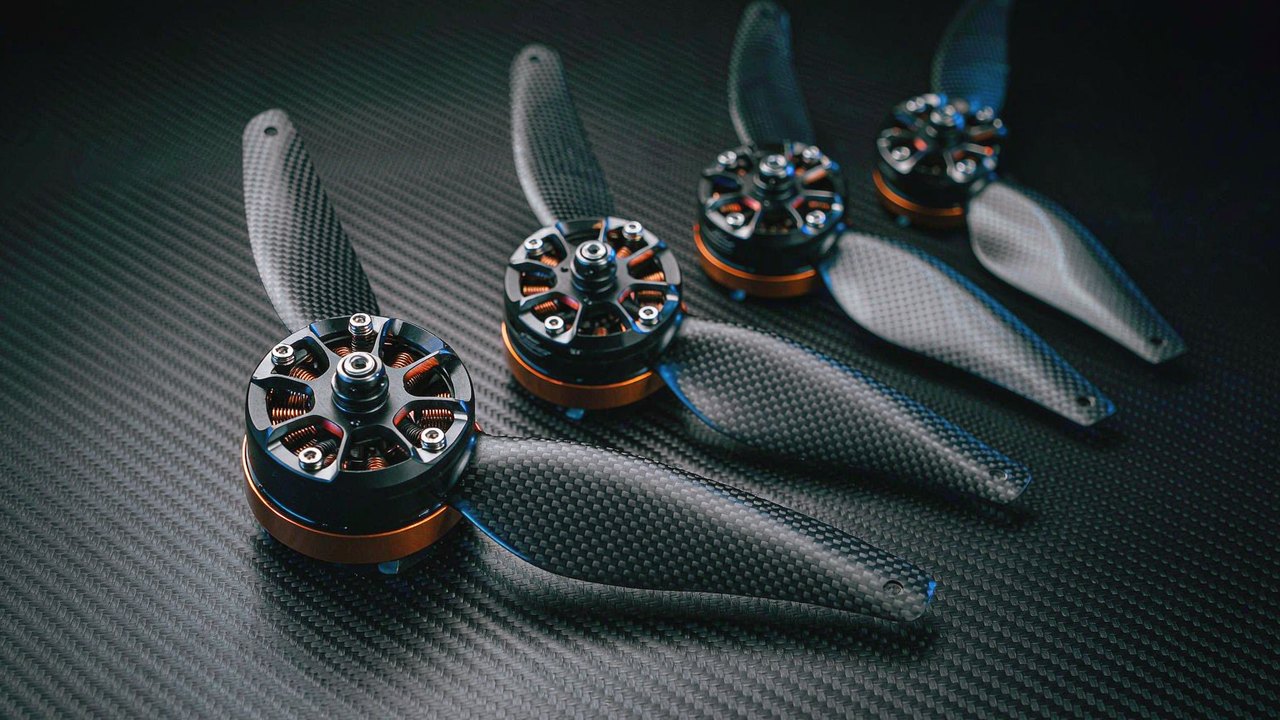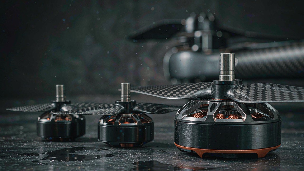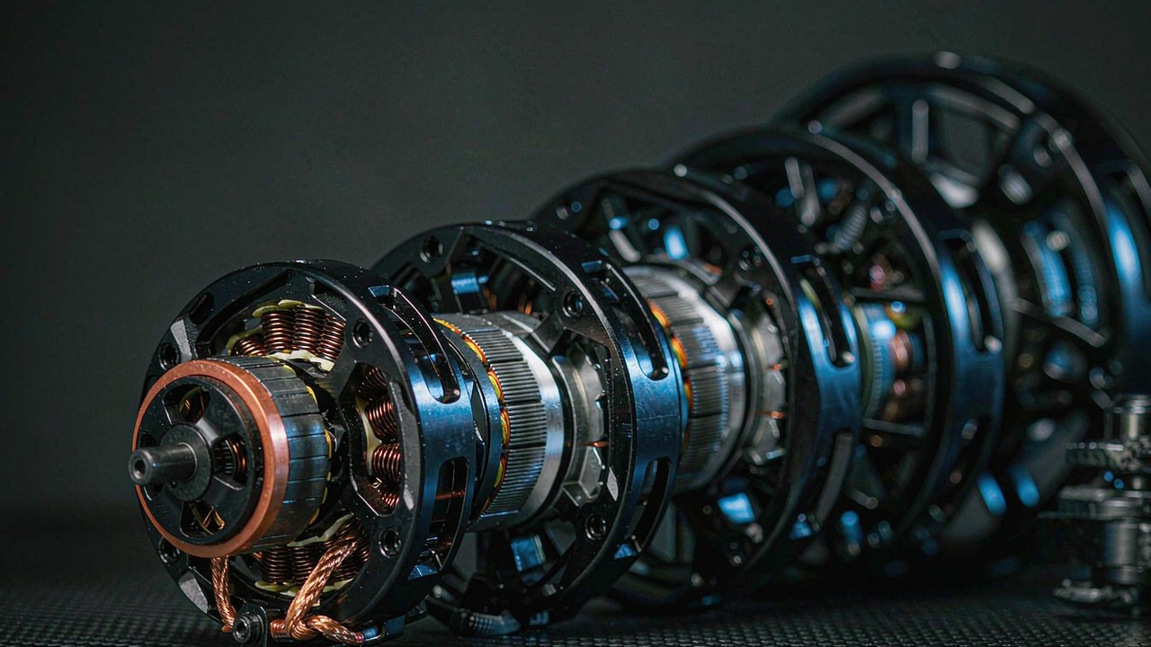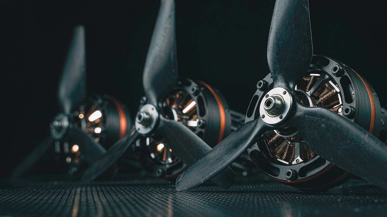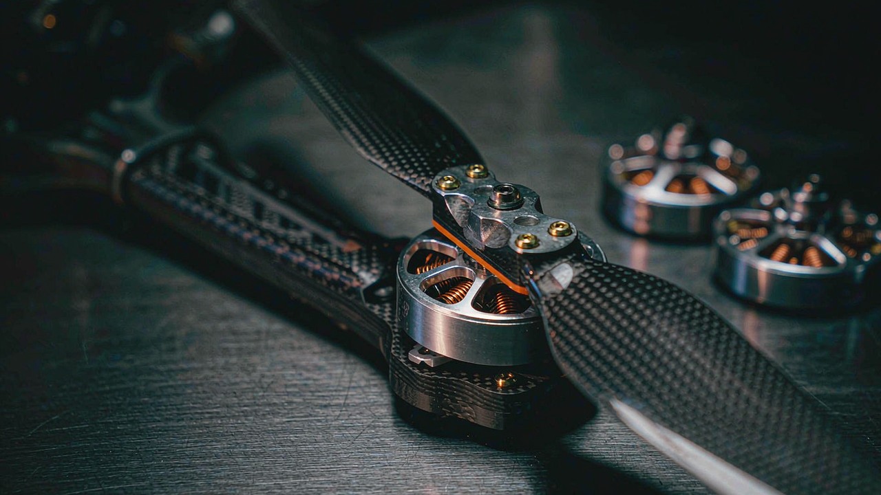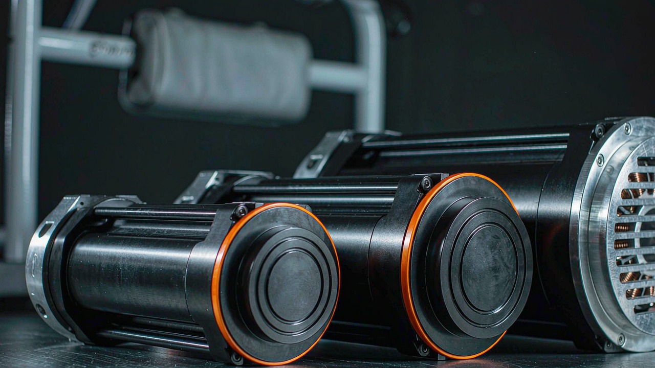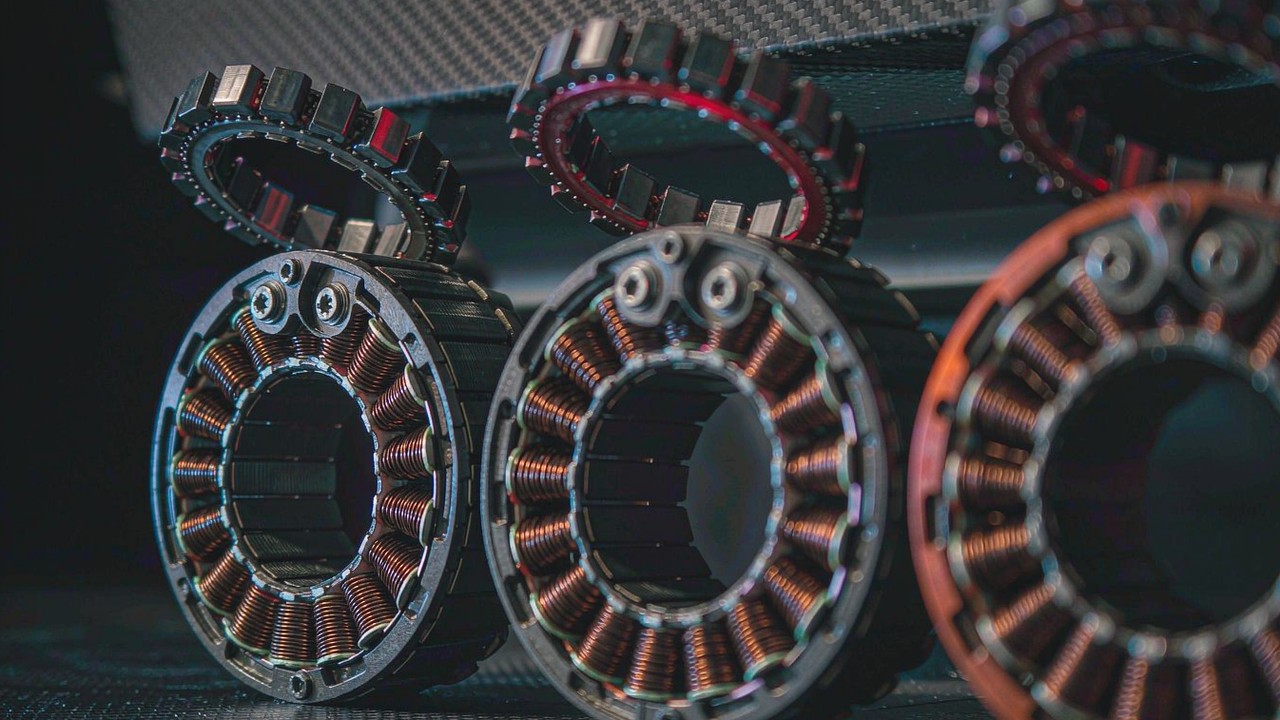
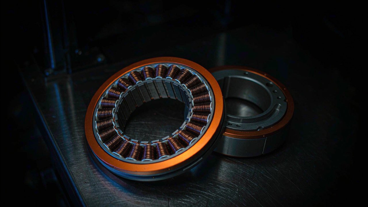
The CubeMars GL gimbal motors are all low-KV direct-drive units built to hold a camera still, so the voltage figure on the label is easy to read past. In this range it is the line that separates two axis sizes: the compact 16 V units drive light camera axes, and the 24V gimbal motors drive the large-diameter axes that carry heavier payloads - and the gap between 16V gimbal motors and 24V gimbal motors is wider than the two numbers suggest. Choosing between the two is less a question about volts than a question about which axis the motor has to move.
What follows sets out what the rated voltage figure does and does not settle, compares seven of the direct-drive models currently listed in the ToBMS Gimbal Motors category across the two voltage classes, and shows where the decision actually turns. Every figure is taken from the ToBMS product record or from the manufacturer’s published specification - none of it is estimated, and no CubeMars GL gimbal motor figure here is inferred from a similar model.
Quick Answer
The 16V gimbal motors and the 24V gimbal motors in the GL range are split by axis size rather than by performance tier. Three of the 16 V models - GL35, GL40 and GL40 II - run from 90 g to 125 g with 0.15 Nm to 0.25 Nm of rated torque, sized for light camera axes where the envelope around the camera is tight. Four of the 24 V models - GL60, GL60 II, GL80 and GL100 - run from 230 g to 698 g with 0.6 Nm to 3 Nm rated torque and 1.5 Nm to 7.7 Nm peak, sized for the heavier camera and sensor-head axes. Rated voltage here describes the bus a motor is specified against and the winding that goes with it; it is not a torque rating, and a higher gimbal motor bus voltage is not by itself a better one. A larger axis needs more torque, and more torque at a low KV on a direct-drive motor means a larger rotor and a lower-KV winding, which in this range is paired with a 24 V bus. Payload and axis size therefore settle the voltage class first, and the voltage figure confirms it afterwards.
What 16V and 24V mean on a gimbal motor
On a gimbal motor the rated voltage is a winding specification rather than a system limit, and the difference matters as soon as the motor is put next to a battery and a driver. For 16V gimbal motors and 24V gimbal motors alike, the figure describes the winding rather than the platform it ends up on.
The Rated Voltage field as the manufacturer publishes it
CubeMars publishes a Rated Voltage (V) line for every model in the GL range, and its value is one of three numbers: 12 V, 16 V or 24 V. That line states the winding the manufacturer wound and tested the motor with, and the current, speed and torque figures published beside it belong to the same operating point. It is worth reading the field together with the rest of the performance table rather than on its own, because one motor family can be published with more than one voltage panel. The GL60 II KV28 is the clearest example in this range: the manufacturer’s page carries a Working Voltage (V) 16 panel and a Rated Voltage (V) 24 panel, and the two panels do not carry the same current, speed or torque figures. The ToBMS record follows the rated panel - 24 V, 1.54 A, 319 rpm, 0.6 Nm rated and 1.5 Nm peak - and states it as the rated voltage. Where a datasheet presents more than one voltage panel, the panel matching the Rated Voltage line is the one consistent with the published rated figures, and for 24V gimbal motors that is the panel the comparison further down follows.
Why a gimbal axis runs at a low bus voltage
A stabiliser axis holds a camera against gravity and corrects small disturbances; it does not have to accelerate anything quickly. A winding made for a low bus voltage at a low KV produces its torque at a modest current and a low speed, which is the operating point the axis spends its life at. Raising the bus voltage on the same motor raises the speed available at a given current, but it does not raise the rated torque, and on a direct-drive axis the extra speed is rarely the binding constraint. That is why the split across these models follows diameter rather than performance tier: the larger the rotor, the more torque it makes at a low KV, and the more of that torque the axis draws before speed becomes relevant at all. 16V gimbal motors are wound for small rotors and modest currents; 24V gimbal motors are wound for larger rotors that make their torque without pushing the current beyond what a compact driver can hold continuously. In practice the gimbal motor bus voltage is a consequence of the rotor size rather than an input to it.
When bus voltage decides the pick, and when it does not
Bus voltage decides the pick when an axis has to be matched to a supply that already exists. A handheld rig on a smaller pack and an airframe on a larger one present different buses, and while a low-KV motor will turn on either, the current needed for a given torque scales with the voltage, so the driver and the harness have to be sized for the bus that is actually available. Bus voltage does not decide the pick when payload is the open question. A 0.25 Nm axis and a 3 Nm axis are not alternatives at any voltage - the first is a small camera head and the second is a cinema-grade axis - and no change of bus moves one into the other. 16V gimbal motors and 24V gimbal motors will both run from a bench supply that suits neither label, so the useful reading is to treat the gimbal motor bus voltage as a constraint that has to be satisfied and the torque and mass figures as the ones that choose the motor.
16V gimbal motors: compact axes for light camera payloads
Three of the GL models are specified at 16 V, and all three sit at the light end of the range. They are the 16V gimbal motors: the units a small camera head, a compact stabiliser or a lightweight pointing stage would use, and they share the same set of limits.
GL35 KV100: a 90 g axis with 0.46 Nm of peak torque
The GL35 KV100 is the smallest of the 16V gimbal motors: 90 g in a Ø41.8 × 21 mm body, with 0.15 Nm rated and 0.46 Nm peak torque, 1.3 A rated and 4 A peak current, and 13 W of rated power. It is a 7 pole-pair design running to 815 rpm rated with a 1320 rpm no-load speed, and its recorded phase-to-phase resistance is 3.6 Ω, a figure that matters for heat while holding rather than for efficiency at speed. On a compact camera axis the relevant question is not how fast the motor turns but whether 0.15 Nm of continuous torque covers the payload at the worst-case orientation.
GL40 and GL40 II: two 16 V windings on a 0.25 Nm axis
The GL40 KV70 and the GL40 II KV82.5 share a rated torque of 0.25 Nm and a 14 pole-pair layout, and both are 16 V units, but they reach that figure along different routes. The GL40 is the lighter and slower of the two at 107 g: 0.5 Nm peak, 1.62 A rated and 3.3 A peak current, 430 rpm rated with a 1015 rpm no-load speed, and 12 W of rated power. The GL40 II is 125 g with a higher 0.68 Nm peak, 1.88 A rated and 5.22 A peak current, 697 rpm rated and a 1388 rpm no-load speed. Both sit on the same 16 V bus and both hold 0.25 Nm continuously, so a decision between two 16V gimbal motors that share one continuous rating turns on the transient and the speed range rather than on the voltage class: the second generation trades 18 g of mass for a higher peak torque and a wider speed range, which matters on an axis that has to slew between positions rather than simply hold one.
What the 16V gimbal motors share as a group
Across the three 16 V models the pattern is consistent: 90 g to 125 g, 41.8 mm to 46.5 mm in diameter, 0.15 Nm to 0.25 Nm rated and 0.46 Nm to 0.68 Nm peak, with rated speeds of 430 rpm to 815 rpm. None of the 16V gimbal motors carries a rated power figure above 13 W. That is what the group is in this range - a compact, low-power, low-cogging axis for a light camera, sized so that the mass carried at the end of the gimbal chain stays small. Running one on a 24 V supply is entirely possible, but it does not turn the motor into a large-axis unit; it only changes how much current the driver has to deliver for the same torque.
24V gimbal motors: the large-axis class
Four of the 24V gimbal motors span 230 g to 698 g and cover the axes that carry a real camera payload. Every one of them shares the same 24 V rating, and the differences between them sit in the rotor rather than in the winding. Above 24 V there is nothing in this range; below it sit the compact units already covered.
GL60 II KV28: 1.5 Nm peak in a 276 g body
The GL60 II KV28 sits at the lower end of the 24 V group: 276 g in a Ø70.5 × 33.6 mm body, with 0.6 Nm rated and 1.5 Nm peak torque, 1.54 A rated and 4.09 A peak current, and a rated speed of 319 rpm. Its winding is recorded with 5.8 Ω of resistance and 6 mH of line inductance, and its configuration as 24N28P. That slot-and-pole layout is the specification worth noting on a slowly moving axis, because more slots and poles generally mean a smaller cogging step and smoother torque delivery - the requirement on a camera axis that has to creep rather than run. It is also one of the models whose manufacturer page carries two voltage panels, and the rated figures quoted here are the 24 V ones rather than the 16 V ones, because that is the panel the record follows.
GL60 and GL80: the 0.6 Nm and 1 Nm rated steps
The GL60 KV25 and the GL80 KV30 are the two steps above it in continuous torque. The GL60 is 230 g with 0.6 Nm rated and 1.75 Nm peak, 1.35 A rated and 4 A peak current, 20 W of rated power at 24 V, 310 rpm rated and 14 pole pairs in a Ø69 × 22.3 mm envelope. The GL80 crosses the 1 Nm continuous threshold at 312 g: 1 Nm rated and 2.9 Nm peak, 2.8 A rated and 8.2 A peak current, 48 W of rated power, 450 rpm rated and 21 pole pairs in a Ø87 × 22.3 mm body. Reading two 24V gimbal motors that share a bus and differ by roughly 1.7 times in continuous torque is the step a design takes when moving from a medium camera axis to a heavier one without disturbing the rest of the electrical system.
GL100 KV10: the heavy-payload end of the range
The GL100 KV10 is the largest 24V gimbal motor here: 698 g, 3 Nm rated and 7.7 Nm peak, 2.9 A rated and 7.8 A peak current, and 41 W of rated power in a Ø106.8 × 34.2 mm body with 20 pole pairs and a rated speed of 130 rpm. Its recorded KV of 9.3 is the lowest of the seven models compared, which is what a 3 Nm direct-drive axis on a 24 V bus asks of the winding. At this size the mass shapes the design of the whole gimbal rather than only its own axis: the motor that carries the camera is itself carried, and on a multi-axis rig that load propagates outward through every stage of the assembly.
16V gimbal motors and 24V gimbal motors, side by side
The table places seven of the direct-drive models currently listed in the ToBMS Gimbal Motors category next to each other, grouped by rated voltage and ordered by mass within each group.
| Model | Rated Voltage | Rated Torque | Peak Torque | Rated Speed | Envelope | Weight |
|---|---|---|---|---|---|---|
| GL35 KV100 | 16 V | 0.15 Nm | 0.46 Nm | 815 rpm | Ø41.8 × 21 mm | 90 g |
| GL40 KV70 | 16 V | 0.25 Nm | 0.5 Nm | 430 rpm | Ø46.5 × 21.5 mm | 107 g |
| GL40 II KV82.5 | 16 V | 0.25 Nm | 0.68 Nm | 697 rpm | Ø46.1 × 33.5 mm | 125 g |
| GL60 II KV28 | 24 V | 0.6 Nm | 1.5 Nm | 319 rpm | Ø70.5 × 33.6 mm | 276 g |
| GL60 KV25 | 24 V | 0.6 Nm | 1.75 Nm | 310 rpm | Ø69 × 22.3 mm | 230 g |
| GL80 KV30 | 24 V | 1 Nm | 2.9 Nm | 450 rpm | Ø87 × 22.3 mm | 312 g |
| GL100 KV10 | 24 V | 3 Nm | 7.7 Nm | 130 rpm | Ø106.8 × 34.2 mm | 698 g |
Rated voltage, rated and peak torque, rated speed, envelope and mass as carried in the ToBMS product record and published by the manufacturer. The KV held in that record is the manufacturer’s measured speed constant, and it differs from the figure used in several product names (GL35 KV100, GL40 KV70, GL60 KV25, GL80 KV30, GL100 KV10) while matching it for the GL40 II KV82.5 and the GL60 II KV28; for a speed or current calculation the manufacturer’s current datasheet is the authoritative source.
The split is clean. Every 16V gimbal motor in this range is under 125 g and under 0.7 Nm peak; every 24V gimbal motor in this range is at least 230 g and at least 1.5 Nm peak. The two classes do not overlap on either figure, so the table reads as two blocks rather than as one continuous range. Rated torque rises from 0.15 Nm to 3 Nm across the seven models, a factor of 20, while mass rises from 90 g to 698 g, a factor of about 8, and peak torque from 0.46 Nm to 7.7 Nm.
The KV recorded for each model tells the same story from the other direction. The lowest values belong to the largest motors - 9.3 for the GL100 and 21.5 for the GL60 against 63.5 and 82.5 for the two lightest 16V gimbal motors. A low KV at a given bus voltage means more torque per amp, and the 24V gimbal motors in this range use exactly that to make their torque at a current a driver can hold continuously rather than at a transient peak.
Below these two classes sits a third, smaller bus voltage. The 12 V GL30 KV290 is a 41 g unit with 0.08 Nm rated and 0.28 Nm peak torque in a Ø34.5 × 15.7 mm body, and it is kept out of the table above because a 12 V axis is answering a different question from the one 16V gimbal motors and 24V gimbal motors are asked to answer.
How the choice tracks payload and duty
Once the choice between 16V gimbal motors and 24V gimbal motors is settled, three questions decide the model inside it.
Payload mass and the axis a motor has to hold
The torque an axis needs is set by the mass it carries and the distance from the axis centre to that mass, and it is the static hold at the worst-case orientation that sets the floor. A camera that is light but mounted far from the axis can demand more torque than a heavier one mounted close to it, which is why the envelope of the gimbal matters as much as the mass of the payload. Across these models the continuous range runs from 0.15 Nm on the GL35 to 3 Nm on the GL100, and the camera each one suits follows directly from that figure rather than from the voltage label it carries. The calculation is the same for 16V gimbal motors and for 24V gimbal motors; the class changes the rotor, not the arithmetic.
Continuous torque, peak torque and the gap between them
Rated torque is the figure an axis can hold within its thermal limits, and for a stabiliser carrying a camera that is the number that decides whether the payload is safe. Peak torque is the maximum the manufacturer specifies under defined conditions - useful for checking the transient when an axis has to arrest a movement or react to a disturbance - but it is bounded by winding temperature and magnet margins rather than by mechanical strength, so it is not a load-holding rating. The gap between the two is narrow across this range: about 2:1 on the GL40 and roughly 3:1 on the GL35, with the 24V gimbal motors sitting near 2.5:1 to 2.9:1 and the 16V gimbal motors at a similar ratio. A narrow gap is characteristic of a motor built to hold rather than to sprint.
Duty across a shooting day
A camera axis may hold a heavy camera against gravity through an entire take rather than for a few seconds, so the duty is continuous within thermal limits and the rated current is the figure that sets how much heat the winding produces while holding a pose. Rated current across the seven models runs from 1.3 A to 2.9 A, which is modest in absolute terms but continuous for the length of a working day. Where a gimbal is battery powered this is what sets endurance; where it is fed from a tether, it sets the cable and driver specification. Either way it is the 16V gimbal motors and the 24V gimbal motors with the lowest rated current for their torque that last the longest between charges.
Supply, driver and integration
Rated voltage is a property of the motor; the bus is a property of the platform, and the two have to be reconciled before the axis is built. Both 16V gimbal motors and 24V gimbal motors are specified against a nominal bus, and the platform brings its own.
Bus voltage in the system, not only on the label
A motor specified at 16 V will run on a 24 V bus if the driver’s current limit, commutation and control loop are set for the winding, and a motor specified at 24 V will run on a 16 V bus with a lower speed ceiling. What changes in either direction is the current required for a given torque, so the constraint that actually bites is the driver’s continuous current rating rather than the nominal bus voltage. Reading the rated voltage line as the winding the manufacturer tested means the published current, speed and torque figures stay valid; running 24V gimbal motors on a lower bus keeps the torque but costs speed, and running 16V gimbal motors on a higher bus keeps the torque but asks more of the driver’s thermal design. A gimbal motor bus voltage that does not match the pack is a driver-sizing question rather than a motor question.
The drive and control electronics behind each class
These motors need a drive that can commutate at the pole count and speed they run at, and that supports the control loop a stabiliser requires - typically field-oriented control with high-resolution position feedback. The pole counts behind 24V gimbal motors run to 21 here, so the electrical frequency at speed is several times the mechanical frequency and the drive’s update rate has to be adequate for it. Treating a gimbal motor as a drop-in replacement for a propulsion motor on an arbitrary ESC is a common source of unexplained vibration, and it is the reason the models that publish a driving method in the ToBMS record all name field-oriented control.
Hollow shaft and the slip-ring path
A camera cable has to reach the payload, and on a rotating axis it has to be routed somewhere. Two options exist: pass it through the axis, or let it loop outside and flex with every movement. The first requires a motor whose drawing includes a through-bore; the second puts a fatigue life on the harness and limits how far the axis can turn in one direction before the loop is wound up. The ToBMS record does not carry a bore dimension, so this is a drawing-level check against the manufacturer’s documentation for the specific model rather than a column that can be compared in the table above. Four of the 24V gimbal motors are the ones where the question arises most often, simply because they sit on the axes that carry the most cable.
Where each voltage class is put to work
Both classes end up on a stabilised camera axis; what differs is the platform and the payload behind it. The 16V gimbal motors suit compact handheld rigs, small sensor heads and lightweight pointing stages, where the axis envelope is small and the mass carried at the end of the gimbal chain has to stay low. The 24V gimbal motors suit the larger handheld and drone-mounted rigs gathered under Gimbal System, and the cinema and sensor-head axes, where the payload is heavy enough that a low-KV, large-diameter rotor is what carries it without a gearbox. Where the payload grows, the larger class takes over, and the gimbal motor bus voltage follows the same line.
The same class of motor is also a natural fit for slow, precise motion outside camera work, and the wider platform covers those duties through the Robotic Actuators and Quasi Direct Drive Actuators categories, where smooth torque at low speed is combined with a reduction stage and an integrated controller. The principle is unchanged between the two: the 16V gimbal motors and the 24V gimbal motors are chosen for how they hold, not for how fast they turn.
Selection checklist
Gimbal motors are usually the last components chosen and the hardest to change once the cage geometry is machined, so these checks are worth running before drawings are released. Because 16V gimbal motors and 24V gimbal motors differ mainly in axis size, the checklist is the same for both.
Torque, duty and the worst-case orientation
- Calculate the static torque the axis must hold with the camera at its worst-case orientation, including the lever arm from the axis centre, and compare it against rated torque.
- Check the transient case against peak torque - an axis arresting a movement or reacting to a disturbance - remembering that peak is a thermal limit rather than a mechanical one.
- Confirm rated and peak current against the driver, and check continuous current against endurance on any battery-powered rig.
Voltage, drive and controller compatibility
- Decide the bus the platform will actually carry, then choose between the 16V gimbal motors and the 24V gimbal motors on that basis rather than the other way round.
- Confirm the pole count and maximum speed against the drive’s commutation capability and update rate.
- Verify that the axis is genuinely direct drive. Any gearing added between the motor and the payload reintroduces the backlash this class was chosen to avoid.
Envelope, mass and the hollow bore
- Check the envelope against the space available around the camera, remembering that these motors are wide and shallow by design.
- Add up mass along the chain from the camera outward; on a multi-axis rig the small motors are carried by the large ones.
- Resolve the cable route before the cage design is frozen, and confirm the bore dimension from the manufacturer’s drawing if the cable is to pass through the axis.
Frequently asked questions
QWhat is the difference between a 16V gimbal motor and a 24V gimbal motor?
In this range the difference is axis size rather than performance tier. The 16V gimbal motors in this range - GL35, GL40 and GL40 II - run from 90 g to 125 g with 0.15 Nm to 0.25 Nm of rated torque and are built for light camera axes. The 24V gimbal motors in this range - GL60, GL60 II, GL80 and GL100 - run from 230 g to 698 g with 0.6 Nm to 3 Nm of rated torque and are built for heavier camera and sensor-head axes. The voltage figure states the winding the manufacturer tested, and the published current, speed and torque figures belong to that winding.
QWhich bus voltage suits a larger camera axis, 16 V or 24 V?
24 V, in this range, because of what the voltage class correlates with rather than because of the voltage itself. A larger axis needs more continuous torque, and a direct-drive motor makes more torque through a larger rotor and a lower-KV winding - the same combination the manufacturer specifies against a 24 V bus. Four of the 24V gimbal motors here hold 0.6 Nm to 3 Nm continuously against 0.15 Nm to 0.25 Nm for the 16V gimbal motors, so the payload decides first and the bus follows.
QCan a 24V gimbal motor be run at 16 V?
Yes, within the driver’s limits. Torque at a given current is set by the winding rather than by the nominal bus, so 24V gimbal motors will still produce their rated torque on a 16 V bus; what falls is the speed available at that current, because the speed ceiling scales with the bus. The practical checks are the driver’s minimum input voltage, its continuous current rating, and whether the control loop still behaves at the lower speed. Running 16V gimbal motors on a 24 V bus keeps the torque and costs nothing in speed, but it asks more of the driver’s thermal design at a given current limit.
QDoes a higher bus voltage mean more torque in a gimbal motor?
No. Torque comes from the winding and the current the driver can push through it, not from the bus voltage on its own. Raising the bus on the same motor extends the speed range available at a given current; it does not raise rated torque. The reason the large 24V gimbal motors in this range make more torque than 16V gimbal motors is that they carry larger rotors and lower-KV windings, and the manufacturer specifies those windings against a 24 V bus - the voltage is the consequence of the design, not the cause of the torque.
QHow many lithium cells match a 16 V or a 24 V gimbal motor?
The cell count follows the nominal bus rather than the motor. Counting a lithium cell at roughly 3.7 V gives about 15 V for four cells and about 22 V for six, so a four-cell pack sits in the 16 V class and a six-cell pack in the 24 V class - but the two figures are nominal, a fully charged pack is well above them, and it is the driver’s input range that finally decides. The ToBMS record for these models does not carry a cell count, so the pack is matched against the driver specification rather than against a gimbal motor bus voltage label.
QWhen does bus voltage stop mattering in a gimbal motor?
Once the axis has been sized and the driver chosen, the voltage class has done its work. A gimbal axis is selected on continuous torque at the worst-case orientation and on the envelope it has to fit; the voltage figure only describes the winding that delivers those figures and the bus it was specified against. The exception is the drive: pole count, current rating and update rate all have to match the winding, and that match is where a voltage-class decision turns into a real constraint rather than a label on a datasheet.
Official resources
CubeMars publishes a full specification page for each model in the GL range, covering performance parameters, drawings and control documentation, and the manufacturer remains the authoritative source for cogging figures, drive recommendations and current firmware. The gimbal motor range on the manufacturer’s site is the place to confirm the winding a specific model is specified against, including where a page carries more than one voltage panel. ToBMS keeps the discovery layer searchable and comparable, with the figures in the table above held in the Gimbal Motors category record.
Where to go next
If the goal is to shortlist rather than to research, three tools on the platform do the work in sequence. Explore the full Gimbal Motors category to see every model and specification side by side, filter candidates by torque, voltage and mass in Select, then place them against each other in Compare Products. Where a slow, precise axis needs a controller and a reduction stage built in, the Quasi Direct Drive Actuators category is the integrated counterpart to this range.
For the wider picture of the class - how cogging, pole count and direct drive shape a stabiliser axis, and how the whole GL range compares as a group - Gimbal Motors: Low-KV Direct Drive for Stable Camera Platforms covers the ground this article does not.
The short version: size the axis on continuous torque at the worst-case orientation, confirm the transient against peak torque, match the winding to the bus the platform actually provides, then let payload and envelope choose between the 16V gimbal motors at 90 g and the 24V gimbal motors at 698 g. On a direct-drive axis there is no gearing to correct a mistake made in any of those four.