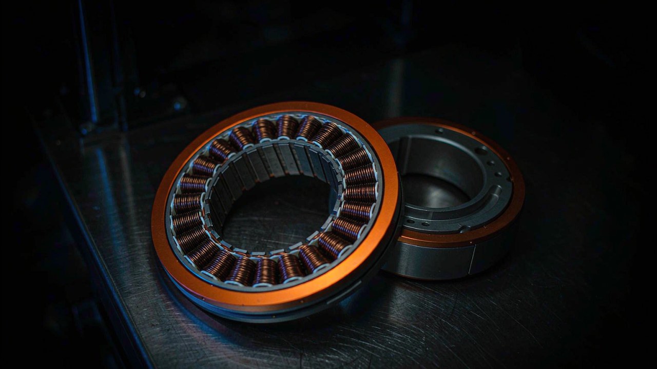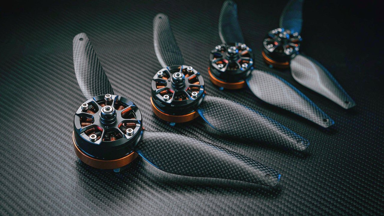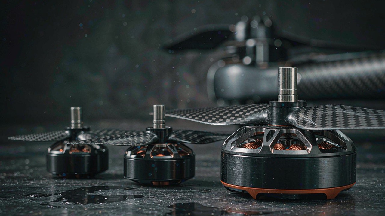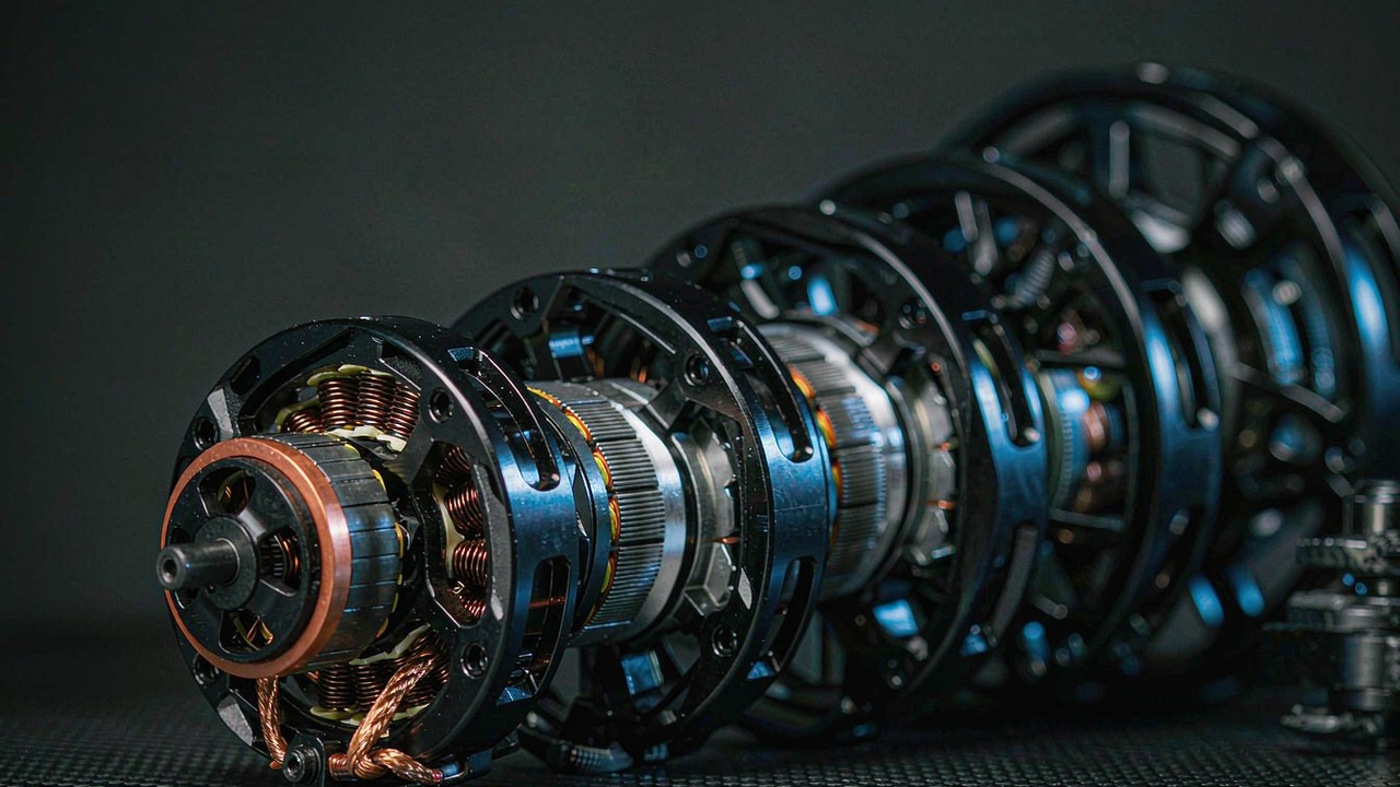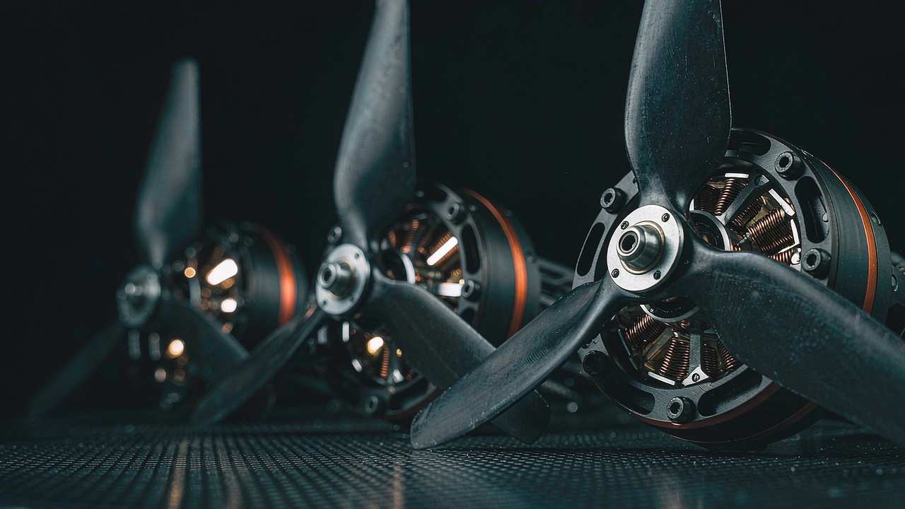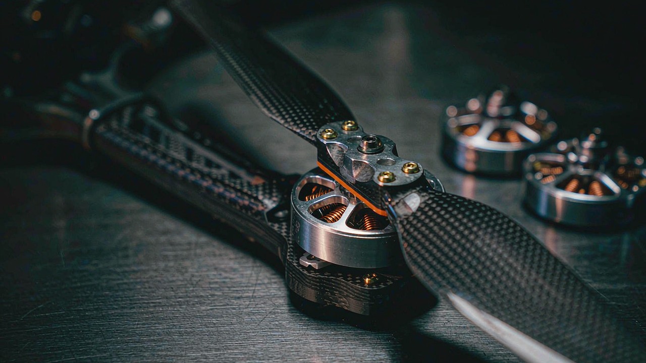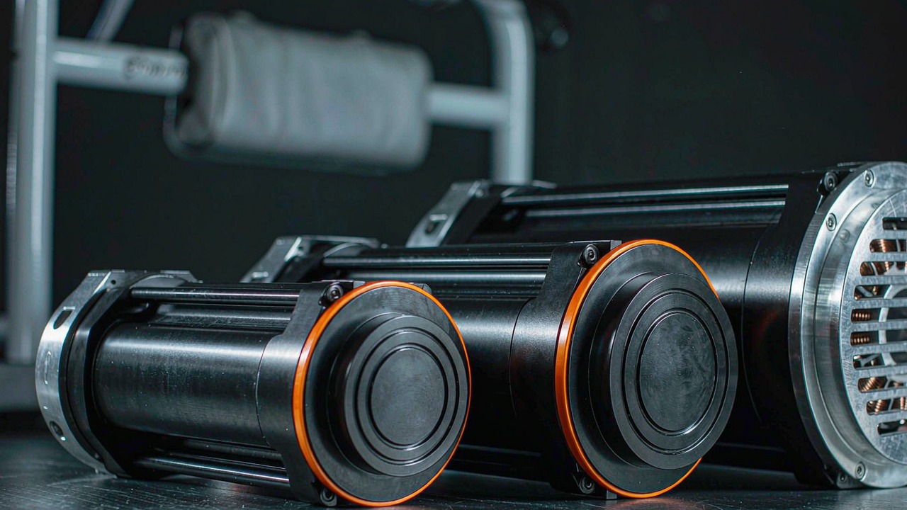
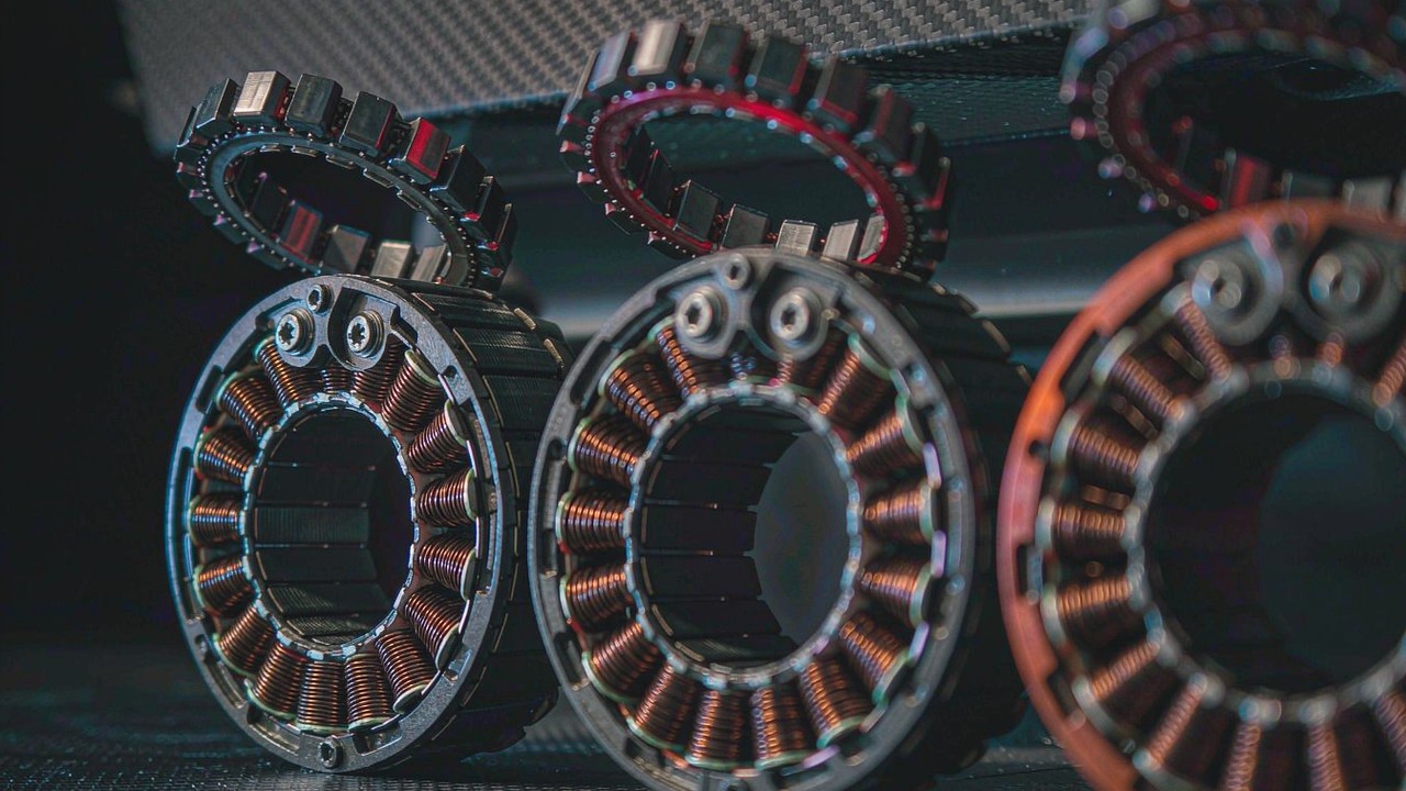
A high torque frameless motor is not a separate class of machine. It is the same stator-and-rotor kit as any other frameless BLDC motor, sized until the published torque figure is large enough to carry a working joint rather than a fingertip. What changes as the size climbs is the price attached to that figure: the current the drive has to deliver, the heat that current puts into the winding, the mass the joint then has to accelerate, and the diameter the surrounding structure has to accommodate. This guide follows that chain through the published record for six of the kits listed in the Frameless Torque Motors category, from the 248 g RO60 KV115 to the 710 g RO100 KV55.
Quick Answer
A high torque frameless motor is identified by three published figures read together, not by one number. Rated torque is the continuous figure a joint can hold without the winding reaching its thermal limit. Peak torque is a short excursion the drive can command but the winding cannot sustain. The maximum torque-to-weight ratio published for these kits then separates them more sharply than torque alone does, running from 9.3 Nm/kg on the RI80 V2.0 KV75 to 16.9 Nm/kg on the RO100 KV55. The six kits in this comparison span 0.8 Nm to 4 Nm rated and 2.4 Nm to 12 Nm peak, between 248 g and 710 g, with rated currents from 7.1 A to 20 A. Torque therefore arrives with a current bill, a heat bill and a mass bill, and the practical question is which of the three the joint can pay.
What "high torque" means on a frameless kit
The phrase describes a position in a published range rather than a technology. Across this category the published rated torque runs from 0.024 Nm to 4 Nm, and the six kits gathered here occupy the upper part of that spread. Reading them correctly depends on keeping two torque figures apart and on noticing that a fourth quantity - mass - moves independently of both.
Rated torque is the figure a joint can hold all day
Rated torque is the largest torque the manufacturer publishes for continuous operation. On the RO series the manufacturer states this directly as a continuous torque: 0.8 Nm for the RO60 KV115, 1.3 Nm for the RO80 KV105 and 4 Nm for the RO100 KV55. The RI series publishes the same quantity under the heading of rated torque, at 0.94 Nm for the RI70 KV95, 1.45 Nm for the RI80 V2.0 KV75 and 1.76 Nm for the RI100 KV105. A joint that holds a pose, resists gravity or carries a standing load is spending rated torque, and the winding heat that comes with it is generated for as long as the pose is held. This is the figure that sizes the winding and, in the end, the motor.
Peak torque is a short excursion, not a working point
Peak torque is what the kit can deliver for a brief interval, and the ratio between the two figures is the clearest warning the record contains. The RI80 V2.0 KV75 publishes 1.45 Nm rated against 4.1 Nm peak, a factor of about 2.8. The RO100 KV55 publishes 4 Nm rated against 12 Nm peak, a factor of 3. A joint that spends its working life near the peak figure is spending a number the winding was not rated to sustain. Peak torque is the right figure for a step response, a fall arrest or a momentary lift; rated torque is the right figure for everything that happens after the transient has decayed.
Two kits of similar mass can sit a whole step apart
The RO60 KV115 and the RI70 KV95 are close in mass at 248 g and 270.4 g, yet they publish different continuous figures, 0.8 Nm and 0.94 Nm, from different layouts and at different bus voltages. The published maximum torque-to-weight ratio makes the same point more compactly: 9.68 Nm/kg for the RO60 KV115 against 9.91 Nm/kg for the RI70 KV95, and 11.36 Nm/kg for the RO80 KV105 against 9.3 Nm/kg for the RI80 V2.0 KV75. Mass alone does not identify the higher-torque kit, and neither does diameter. The figure that does is the one the manufacturer publishes for the winding and the duty.
Where the torque comes from
Torque in a permanent-magnet BLDC motor is produced at the air gap between the magnets on the rotor and the current in the stator slots. Everything the record publishes about a high torque frameless motor is a consequence of how much active material the manufacturer placed at that gap, and of how the winding is arranged.
Magnet and copper, sized by stator diameter
More torque needs more magnet and more copper acting at a larger radius, and radius is the lever arm in the relationship between force at the gap and torque at the axis. That is why the largest kit in this group is also the widest: the RO100 KV55 publishes 4 Nm rated from a 113.5 mm outer diameter and 710 g, while the RO60 KV115 publishes 0.8 Nm rated from 73.8 mm and 248 g. The RI series follows the same rule within its own layout, climbing from 0.94 Nm rated at 76 mm on the RI70 KV95 to 1.76 Nm rated at 104 mm on the RI100 KV105. A frameless kit has no housing to inflate that diameter; the envelope published is the stator and rotor envelope the structure has to accommodate.
Kt is published, and it is the sign of a low-speed kit
The manufacturer publishes a torque constant, Kt, in Nm/A for each of these kits: 0.130 for the RI70 KV95, 0.155 for the RI80 V2.0 KV75, 0.129 for the RI100 KV105, 0.094 for the RO60 KV115, 0.087 for the RO80 KV105 and 0.2 for the RO100 KV55. Kt states how much torque the kit produces per ampere of phase current, and it is the single most useful number for reading a high torque kit, because it turns a torque requirement directly into a current requirement for the drive. The trend across the group is also the trend across the technology: the lower the Kt, the more current is needed for a given torque, and the higher the continuous current the drive and the winding have to survive. A high torque frameless motor is, in this sense, a high-Kt machine asked to run at a current the winding can hold.
Pole pairs and what they change at low speed
Pole pair count is published for every kit here: 8 on the RI80 V2.0 KV75, 14 on the RI70 KV95, the RI100 KV105 and the RO60 KV115, and 21 on the RO80 KV105 and the RO100 KV55. More pole pairs means more commutation cycles per revolution and smoother torque at very low speed, which is what a joint that creeps through a small angle under load needs. It also raises the electrical frequency the drive has to handle at a given mechanical speed, which becomes a constraint only at the top of the speed range. For a high torque application the low-speed smoothness is usually the property being bought.
The current and thermal price of torque
Torque is not free at the terminals. Every newton metre is paid for in phase current, and every ampere is paid for in heat inside the winding. The published record shows what that costs across this group.
Bus voltage sets speed, not torque
Bus voltage determines how fast the kit can turn before the back-EMF rises to meet the supply, and that is visible in the published speed columns. The RI kits offer three working points because they accept 24 V, 36 V or 48 V: the RI80 V2.0 KV75 publishes 1135, 1785 and 2430 rpm rated speed and 1480, 2220 and 2960 rpm no-load speed across those buses. The RO kits publish one point each at their rated 48 V, from 3600 rpm on the RO80 KV105 to 2000 rpm on the RO100 KV55. Torque, by contrast, is set by current and by Kt, which is why a joint that needs more torque at a given speed is a winding and current question rather than a voltage question.
Copper loss rises with the square of the current
The heat developed in the winding is proportional to the square of the current flowing through it, so a kit asked to deliver torque at a current it was not wound for heats disproportionately faster. The published peak currents in this group are substantial: 21 A on the RI70 KV95, 27.6 A on the RI80 V2.0 KV75, 38.6 A on the RI100 KV105, 40 A on the RO60 KV115, 50 A on the RO80 KV105 and 62 A on the RO100 KV55. None of those is a continuous figure. They are short excursions, and the gap between a rated current of 7.1 A and a peak current of 21 A on the RI70 KV95 is the thermal headroom the winding has, not a working window.
What the published continuous figure covers
A continuous or rated torque figure is a thermal statement, and it is made against a stated ambient and mounting condition. The RI kits publish an operating ambient temperature of -20 °C to 50 °C, and the RO kits publish the same window. What the record does not carry is the thermal resistance between the winding and the mounting face, which is the quantity that decides how much of the rating survives once the kit is bolted into a structure that conducts heat differently from the manufacturer's fixture. That is a question for the manufacturer, and it is the first one to ask when a joint is expected to hold a high torque continuously rather than occasionally.
Sizing up: envelope, bore and rotor mass
Increasing torque changes three other published quantities at the same time, and in a frameless kit each of them lands on the integrator rather than on the manufacturer.
Outer diameter grows faster than peak torque
Within this group the outer diameter rises from 73.8 mm on the RO60 KV115 to 113.5 mm on the RO100 KV55, a factor of about 1.54, while published peak torque rises from 2.4 Nm to 12 Nm, a factor of 5. The comparison is not a like-for-like substitution between layouts, and the RI series shows the effect at a different rate, moving from 2.68 Nm peak at 76 mm on the RI70 KV95 to 4.95 Nm peak at 104 mm on the RI100 KV105. The reading is still useful: a step up in torque is bought largely with a step up in diameter, and the surrounding structure has to find that room. Where the joint cannot grow radially, the alternative published lever is the winding and the current, not a smaller motor of the same torque.
The hollow bore and where the cables go
Every kit here is built around a hollow centre, and the published bore is a design constraint as much as the outer diameter. The RI80 V2.0 KV75 publishes a through bore of 40.5 mm and the RI100 KV105 publishes 45 mm, while the RI70 KV95 publishes a 38 mm hollow shaft diameter. A bore of that size passes signal and power conductors, a drive shaft, or the body of a harmonic reducer straight through the middle of the joint. Choosing a kit is therefore also choosing the routing that has to live inside the moving assembly for the life of the machine, and a larger bore is one of the few ways to buy harness life without buying a bigger joint.
Rotor mass is the mass the joint has to move
A frameless kit is published as two parts, and the RO series records their masses separately: 105 g rotor and 143 g stator on the RO60 KV115, 148 g rotor and 204 g stator on the RO80 KV105, and 324 g rotor and 356 g stator on the RO100 KV55. The rotor is the half that turns, so its mass, not the total, is what the joint has to accelerate and what its inertia contributes to the loop the drive has to stabilise. The manufacturer publishes that inertia as well, at 1161 gcm² on the RO60 KV115, 2612 gcm² on the RO80 KV105 and 8700 gcm² on the RO100 KV55. For a joint that has to reverse quickly, a lighter rotor at the same torque is worth more than a lighter total.
Mechanical load path and integration
A frameless kit arrives without the parts that usually absorb and transmit load, and in a high torque joint those parts are where the design work sits.
The bearing is the integrator's decision
None of these kits carries its own bearing stack. The stator has to be clamped into a structure that also conducts its heat away, and the rotor has to be mounted to whatever rotates, with a bearing arrangement chosen for the radial and axial loads the joint will actually see. At the torques published in this group those loads are no longer incidental, and the bearing choice, its preload and its own stiffness belong to the machine rather than to the motor. The published mounting provisions are the starting point: the RO kits are supplied with a locating pin and a set of fixing screws in the accessory pack, at M4 on the RO80 KV105 and M5 on the RO100 KV55.
Radial load passes through the joint
Because the kit has no housing and no shaft of its own, the radial load from a belt, a gear or an offset payload does not pass through the motor. It passes through the bearing the integrator provides, and the motor rotor sees only the torque the joint resists. That is one of the advantages of the layout, and it is also a requirement on the surrounding design: the structure has to keep the rotor and the stator concentric through the full load range, because the published air gap is a running clearance rather than a tolerance. Where the joint is asked to carry a person or a heavy arm, the deflection of the supporting structure under load becomes part of the motor's operating condition.
Feedback at standstill
The RO kits are published as supplied with Hall sensors and a temperature sensor, and the RI kits are published with Hall sensors as an option. A joint that holds position under load needs position information while it is not moving, and that is the point at which sensorless estimation becomes least reliable. The choice between a kit with feedback and one without is therefore a decision about what the drive is expected to do at zero speed, and the record states it per kit: the RO60 KV115 Standard, the RO80 KV105 Standard and the RO100 KV55 Standard carry both sensors, while the Lite versions of the same frames are published without them.
The high-torque end of the range
The table below gathers the six kits discussed here on the columns that decide a high torque joint. Every value is the figure the manufacturer publishes for that kit.
| Model | Rated Torque (Nm) | Peak Torque (Nm) | Rated Current (A) | Rated Speed (rpm) | Weight (g) | Diameter (mm) |
|---|---|---|---|---|---|---|
| RI70 KV95 | 0.94 | 2.68 | 7.1 | 1270/1990/2710 | 270.4 | 76 |
| RI80 V2.0 KV75 | 1.45 | 4.1 | 9.4 | 1135/1785/2430 | 411 | 85 |
| RI100 KV105 | 1.76 | 4.95 | 13.6 | 1370/2100/2825 | 500 | 104 |
| RO60 KV115 | 0.8 | 2.4 | 8.5 | 4200 | 248 | 73.8 |
| RO80 KV105 | 1.3 | 4 | 15 | 3600 | 352 | 92.6 |
| RO100 KV55 | 4 | 12 | 20 | 2000 | 710 | 113.5 |
Rated torque, peak torque, rated current, rated speed, weight and diameter as published by the manufacturer (CubeMars). Where a speed entry carries three values, they are the 24 V, 36 V and 48 V working points in that order; the RO kits publish a single point at their rated 48 V. Rated torque is the continuous figure and peak torque is a short-duration value. Winding, thermal and mounting data for each kit are on its manufacturer product page.
Read down the rated torque column and the group divides into three pairs. Two kits publish under 1 Nm, two publish between 1.3 Nm and 1.45 Nm, and one publishes 4 Nm, three times the figure below it. That last gap is the point of the table: a step from 1.76 Nm to 4 Nm rated is not a refinement of the same design, it is a different class of joint, and the mass, diameter and current columns move together with it. Read across instead, and the current column explains why the largest kits are not simply the stronger ones. The RO100 KV55 asks for 20 A continuously to hold its 4 Nm, against 8.5 A for the RO60 KV115 to hold 0.8 Nm, and a drive sized for one is not sized for the other.
RI80 V2.0 KV75 and RI100 KV105: the inner-rotor pair
The two largest RI kits in this group are both built on a 24 V, 36 V or 48 V bus, and both publish three working points rather than one. The RI80 V2.0 KV75 publishes 1.45 Nm rated and 4.1 Nm peak from 411 g and an 85 mm diameter, with a through bore of 40.5 mm and a maximum torque-to-weight ratio of 9.3 Nm/kg. The RI100 KV105 publishes 1.76 Nm rated and 4.95 Nm peak from 500 g and 104 mm, with a 45 mm bore and a ratio of 9.9 Nm/kg. Between them the mass rises by about 22 percent for about 21 percent more rated torque, and the diameter has to grow from 85 mm to 104 mm for that step. The choice between them is largely a question of whether the joint has the radial room for the larger frame.
RO80 KV105 and RO100 KV55: the outrunner pair
The two largest RO kits publish a single operating point at 48 V and are supplied with Hall and temperature sensors as standard. The RO80 KV105 publishes 1.3 Nm continuous and 4 Nm peak from 352 g and 92.6 mm, with a cogging torque of 24 N.mm and a ratio of 11.36 Nm/kg. The RO100 KV55 publishes 4 Nm continuous and 12 Nm peak from 710 g and 113.5 mm, with a cogging torque of 55 N.mm and a ratio of 16.9 Nm/kg, the highest in this group. The RO100 KV55 is the kit that reaches the top of the rated range published for this category, and its 16.9 Nm/kg records that it does so with less mass per newton metre than any other kit here.
RI70 KV95 and RO60 KV115: the step below
The RI70 KV95 publishes 0.94 Nm rated and 2.68 Nm peak from 270.4 g and 76 mm, with a 38 mm hollow shaft and a ratio of 9.91 Nm/kg. The RO60 KV115 publishes 0.8 Nm continuous and 2.4 Nm peak from 248 g and 73.8 mm, with a cogging torque of 15 N.mm and a ratio of 9.68 Nm/kg. Both sit close to 1 Nm continuous, and both are the natural starting point for a joint that needs to carry a working load without the mass and diameter of the largest frames. They also differ in the way their bus behaves: the RI70 KV95 accepts 24 V to 48 V, while the RO60 KV115 is published at 48 V.
CubeMars shows the RI80 V2.0 KV75 driving an inspection platform, which is the working end of the torque range this guide discusses: a joint carrying a real mechanism rather than a test fixture. It is the clearest illustration of what the 1.45 Nm continuous figure buys in a finished machine.
ToBMS video pageWatch on YouTubeMatching torque to a joint duty
The published figures only become a decision once the joint's own duty is written down first. Three quantities, in this order, do most of the work.
Start from the worst-case hold, not the cruise
The figure that sizes the kit is the largest torque the joint has to hold or move repeatedly, together with how long it is held. A joint that supports a static load, resists gravity on a raised arm or holds a position against a spring is spending continuous torque for the entire duration, and the rated column is the one to read. The peak column enters only for transients: an acceleration, a catch, a step command. Writing the two down separately, with a duration against each, is what turns the published rating into a requirement rather than a comparison.
Then the speed at that torque
Torque and speed are not independent, and the published record is organized around that. The RI kits publish a rated speed and a no-load speed for each of three buses, from 1135 rpm rated at 24 V to 2430 rpm rated at 48 V on the RI80 V2.0 KV75, and the RO kits publish one pair each at 48 V. A joint that needs its working torque at a higher speed is asking the kit to run further up the speed range, where the available torque has already begun to fall from its maximum. Fixing the required speed at the required torque, rather than the maximum of each, is what keeps the selection honest.
Then the thermal duty cycle
The last step is the one the record answers least completely. Continuous ratings are published against a stated ambient and a mounting condition, and a joint that holds a high torque for a large fraction of its cycle will sit closer to the thermal limit than one that spends most of its time at rest. The published cogging torque and rated current are useful proxies for how much heat the winding will make at a given duty, but the thermal resistance between the winding and the mounting face is the quantity that decides the outcome, and it is not in the record. It is the first figure to request from the manufacturer before committing a high torque joint to a continuous duty.
Selection checklist
The mechanical envelope
- Write the required continuous torque and the required peak torque separately, with a duration against each.
- Check the published outer diameter and length against the space the joint actually has, before looking at mass.
- Check the published through bore against the conductors, shaft or reducer that has to pass through it.
- Note the published rotor mass and inertia, not only the total, if the joint has to reverse quickly.
The electrical budget
- Convert the torque requirement into a current requirement with the published Kt for the kit being considered.
- Compare that current against the published rated current, not the peak current.
- Fix the bus voltage from the required speed at the required torque, using the published speed columns.
- Confirm the continuous rating against the joint's duty cycle, and ask the manufacturer for the thermal resistance the record omits.
Integration and feedback
- Decide whether the kit is supplied with Hall sensors or without, and what the drive needs at zero speed.
- Size the bearing arrangement for the loads the joint will see, since the kit carries none.
- Plan the heat path from the stator into the structure, because the mounting is the thermal interface.
- Confirm the mounting provisions and fixings published for the specific frame being considered.
Frequently asked questions
QCan a high torque frameless motor run continuously at its peak torque?
The published record separates the two figures for a reason. On the kits in this comparison the peak figure is roughly two and a half to three times the continuous one, 4.1 Nm against 1.45 Nm on the RI80 V2.0 KV75 and 12 Nm against 4 Nm on the RO100 KV55, and the peak figure comes with a peak current that is several times the rated current. Continuous operation belongs to the rated figure. The peak figure is for the intervals where the joint has to accelerate, catch a load or survive a transient, and its safe duration depends on the thermal state of the winding at the moment it is called for.
QDoes a lower KV mean more torque on its own?
Not on its own, and the kits here show why. The RO100 KV55 publishes a KV of 55 rpm/V and 4 Nm continuous from 710 g, while the RO80 KV105 publishes 105 rpm/V and 1.3 Nm continuous from 352 g. The lower KV kits in the group are also the larger and heavier ones, so the torque comes from the active material and the winding together rather than from the KV figure alone. KV sets the speed per volt and the torque per ampere; the amount of torque a kit can hold continuously is set by how much magnet and copper the manufacturer placed at the gap, and by how much heat that winding can shed.
QWhat does a high torque frameless kit leave for the integrator to add?
Everything between the stator and the load. These kits are published as a stator and a rotor with no housing, no bearing and no shaft of their own, so the rotor mounting, the bearing arrangement and its preload, the clamping that holds the stator and conducts its heat away, and the position feedback where the kit is supplied without it are all part of the machine. The record states which kits carry feedback: the RO60 KV115 Standard, the RO80 KV105 Standard and the RO100 KV55 Standard are published with Hall and temperature sensors, and the Lite versions of the same frames are published without.
QIs a heavier kit the higher torque kit?
Not necessarily, and the published torque-to-weight ratios show the difference. The RO80 KV105 publishes 11.36 Nm/kg against 9.3 Nm/kg on the marginally lighter RI80 V2.0 KV75, and the RO100 KV55 publishes 16.9 Nm/kg, the highest ratio in this group. Mass and torque move together across the range as a whole, but two kits built at different frames and layouts can land a full step apart at similar mass. The useful comparison pairs the published continuous torque with the published mass, which is exactly what the torque-to-weight ratio does.
Official resources
CubeMars documents the frameless range on its own site, and each kit in this comparison has an official page carrying its full specification, winding data and mounting drawing. The manufacturer's product range is the entry point, and the two ends of this comparison are documented individually - the RO60 KV115 at the light end and the RO100 KV55 at the heavy end. Product documentation across the platform's categories is collected under Resources. The manufacturer remains the source of truth for winding options, thermal ratings and custom bore enquiries; ToBMS keeps the discovery and comparison layer, and every figure used in this guide is a published value held in the platform's product records.
Where to go next
The closest companion to this guide is Frameless Torque Motors: Choosing a Stator and Rotor Kit for Robot Joints, which reads a frameless kit from the inside out - the stator, the rotor, the two layouts and what each specification column promises. Frameless Torque Motors: 12 Models Compared, From Entry to Performance Tier places the full range side by side by performance band, and BLDC Motors for Exoskeleton: Frameless Torque Motor vs Integrated Actuator takes up the choice between a bare kit and an assembled module for a wearable joint. This guide sits between them, following the torque figure from the winding to the joint.
To shortlist rather than to research, start from the full Frameless Torque Motors category, filter candidates by torque, voltage and mass in Select, then place them against each other in Compare Products. Where the joint should arrive as a sealed module with the reducer and drive already matched, the Robotic Actuators category is the natural next stop.