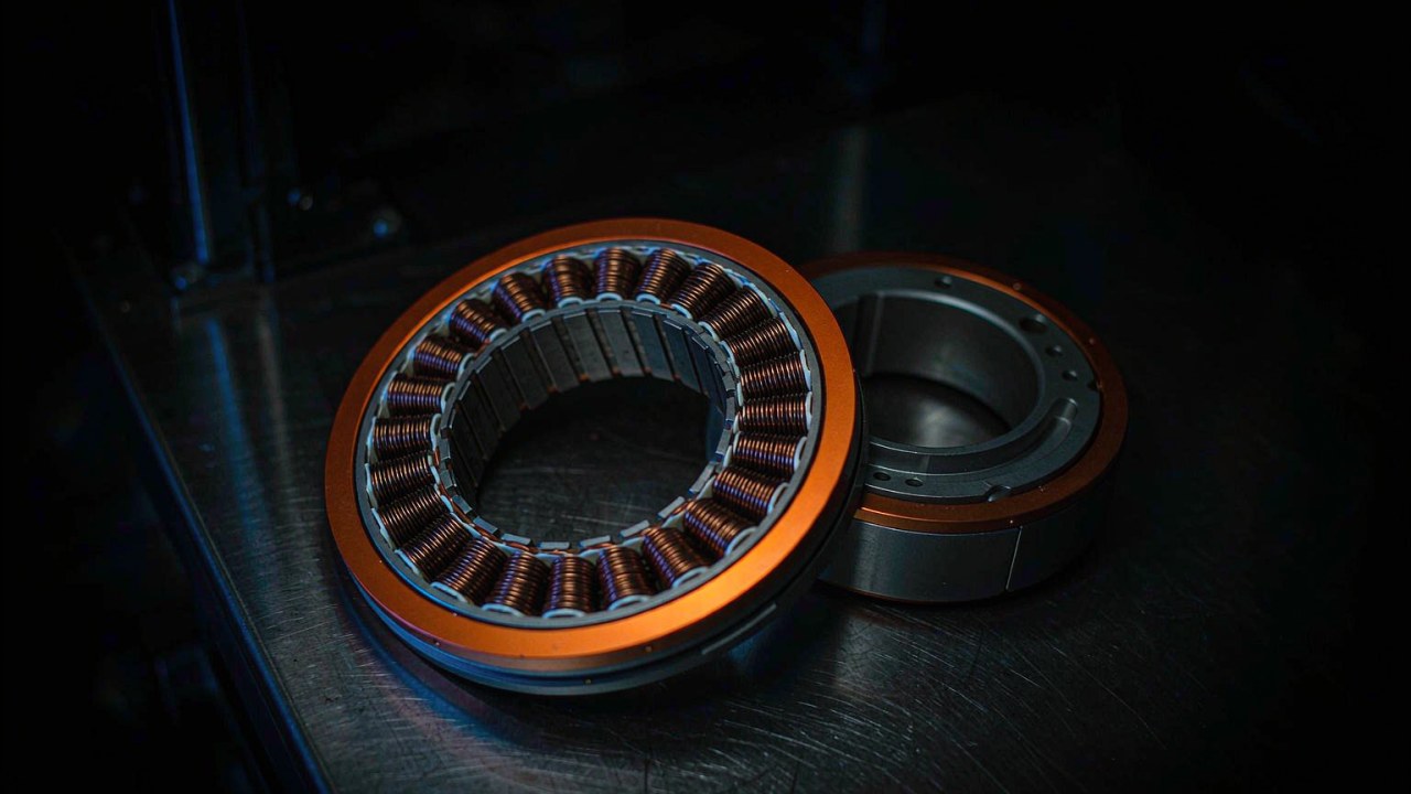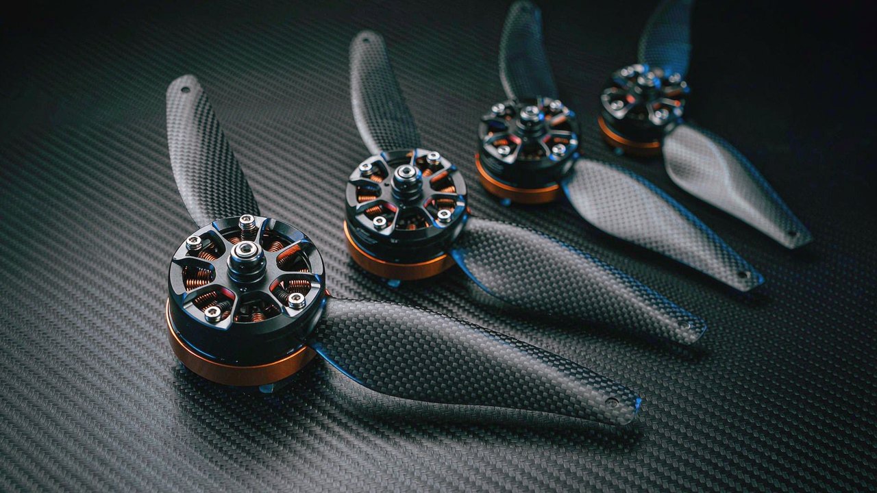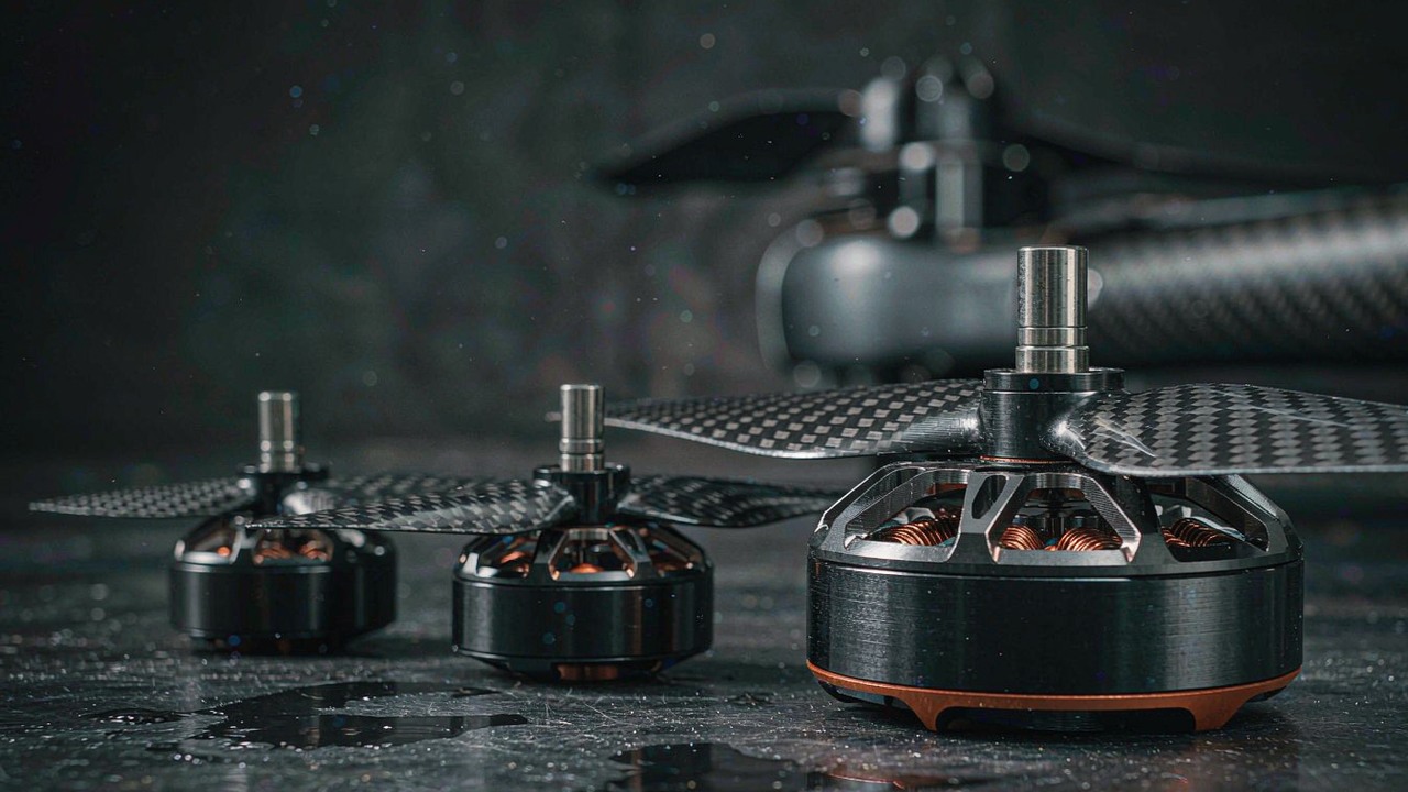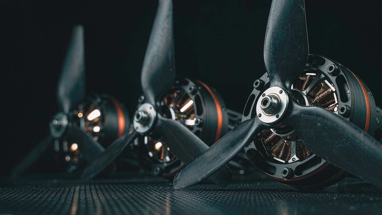
A BLDC Motor for Industrial UAV is chosen for a task that repeats rather than for a single flight, and the eight records currently listed under the Industrial UAV duty show how far apart the two ways of reading a specification can sit. Across the group the KV runs from 80 to 700, the published mass from 128 g to 1740 g, the internal resistance from 17 mΩ to 116 mΩ, the maximum thrust from 1800 g to 36500 g and the published 180 second power from 500 W to 8580 W. That span has to cover a sub-kilogram survey airframe at one end and a platform carrying tens of kilograms of sensor and pack at the other, so the useful question is not which record publishes the largest number, but which one holds its current, its temperature and its thrust margin across the whole mission profile the airframe is built around. This guide reads the eight records against that question, and the same set of models is collected on the Industrial UAV application page.
Quick Answer
An industrial airframe does not spend its life at the point its specification panel is loudest about. It lifts a payload, settles, and then holds a position for minutes at a time, several times a day, for as long as the airframe stays in service. The electrical consequence is that the current drawn at the holding point is paid continuously across the whole mission, while the peak current lasts seconds. A shortlist written against a peak column therefore answers a question the aircraft asks rarely, and leaves the question it asks constantly unanswered.
Three properties carry that duty, and the records below publish them unevenly. Internal resistance is the coefficient on copper loss, which is the loss that runs for the whole mission rather than in bursts. The published cell-count window is what decides the current the winding has to carry for a given shaft power, and a higher bus lowers that current. The published 180 second power is a thermal window rather than a continuous rating, and it is best read as a margin signal between candidates of similar duty rather than as a figure to divide into pack energy.
The eight records divide first at the thrust they publish and second at the bus they are published for. Four of them sit below 3000 g of published thrust and four above 8000 g, and the KV figures follow the same split: the lighter records are published at 400 KV and 700 KV on 3-8S or lower, while every record above 8000 g is published at 170 KV or lower on 6S and above. That division is what the sections below take apart, first as a mission profile, then as a set of platform mass bands, and finally as a sequence of decisions.
What an industrial mission asks of a motor
On an Industrial UAV the mission is a duty before it is a specification, and the difference between it and a hobby flight is a difference of repetition rather than of size. An airframe flown a few times for pleasure and an airframe flown several times a day for a utility share the same physics but not the same failure economics, and the second one is the case the records below have to answer.
Repetition, not a single flight
The distinguishing feature of an industrial duty is that the same mission is flown again, and then again, with short ground intervals between sorties. That matters to the motor because thermal behaviour is a state rather than an event: a winding that reaches a given temperature in one flight starts the next flight from whatever temperature it retained, and an airframe that flies four sorties in an afternoon subjects the insulation and the bearings to an accumulated load that a single flight does not produce. The records published here describe thermal limits over a defined window rather than a duty profile, so the honest reading is comparative: a record published for a higher 180 second power carries more thermal headroom into a repeated mission than one published for less, at the same duty.
Payload that has to survive the whole mission
A camera, a lidar unit or a multispectral sensor has to be held within a stable attitude for the whole of a flight, and stability is an electrical property before it is a mechanical one. Position holding is a control loop that corrects with thrust, and thrust is produced with current, so a gust or a payload shift is answered by a current step at the winding. A propulsion record with a lower resistance answers that step with less copper loss, which keeps the operating point closer to where it was and reduces the transient the attitude controller has to spend energy correcting. Payload survival and winding resistance are therefore connected through the current loop rather than only through the airframe.
What the airframe tolerates in a motor
The records in this group run from 128 g to 1740 g and from a 41.8 mm body to a 147.5 mm one, and those two ranges are packaging constraints as much as performance ones. A boom has a bending stiffness that falls as length rises, a motor mount has a bolt pattern the airframe has to provide, and a heavier outrunner at the end of an arm shifts the inertial properties the flight controller has to model. The mass and envelope columns are not decoration next to the electrical ones; on a repeated mission they set how much of the arm can be built for stiffness rather than for the load the motor itself imposes.
Duty cycle: the number the airframe actually runs at
A duty cycle is the share of the mission each operating point accounts for, and on an industrial airframe it is dominated by the segment that produces the least spectacle. Hover is not the interesting part of a flight to watch, but it is the part the pack pays for, and it is the segment over which the BLDC Motor for Industrial UAV choice is actually made.
Hover share against cruise share
On a rotor-borne airframe the hover segment carries the whole weight of the aircraft on thrust alone, with no wing to share the load, and on an inspection or holding mission that segment is the majority of the flight. On a survey mission the split moves toward a forward leg, but the forward leg on a multirotor is still flown at a high angle of attack on the same rotors, so the current reduction is smaller than the change in airspeed suggests. The practical reading is that the holding point, not the maximum-thrust point, is the operating point the pack is sized against, and every column that describes efficiency at that point is worth more than a column that describes the ceiling.
Repeated climb, not one peak
A utility airframe climbs to working altitude, descends to change a battery, and repeats. Each climb is a high-current event of tens of seconds, and over a working day the number of those events runs into the dozens. That pattern sits between the two conditions a specification panel describes: it is far longer than the instantaneous event a peak current figure covers, and far shorter than the steady state a continuous rating implies. It is also the reason a record published for a higher continuous current is worth more to this duty than a record published for a higher peak, because the climb recurring through the day is what accumulates.
Why a 180 s column cannot stand in for a duty
The published 180 second power is the power a motor can absorb for 180 seconds before its winding reaches the temperature limit set by its insulation class and its mounting. It is a window and a convention rather than a rating the motor holds indefinitely, and it is published at the manufacturer’s own test condition rather than at the airframe’s hover condition. Its usefulness is comparative: a record published at 3180 W carries more current margin than one published at 1600 W when the two are compared at the same duty, and that margin is what a heavier payload or a hotter day consumes. It is not a figure a pack energy budget is divided by, because the conversion from stored energy to time in the air runs through the current at the holding point instead.
Redundancy: the thrust margin a multirotor pays for
The thrust margin a BLDC Motor for Industrial UAV has to carry is a property a fixed-wing aircraft or a helicopter does not have: after the loss of one propulsion unit the multirotor can remain controllable, provided the remaining units have thrust in reserve. That reserve is bought with motor and pack mass, and it is the second constraint that separates an industrial specification from a recreational one.
What happens when one motor stops
On a six-rotor airframe the loss of one propulsion unit leaves five units to carry the aircraft, so the remaining units have to produce about 6/5 of their normal share, an increase of roughly 20 percent, to hold altitude on the opposite side of the frame. That is arithmetic rather than a specification: the number follows from the count of rotors, not from the model chosen. What the model contributes is whether it can produce that share without leaving its published continuous window, because a reserve that exists only inside a 180 second column is available for a descent rather than for a continued mission.
Margin as mass, current and pack size
A thrust margin is not free, because a motor sized to produce more thrust at the same current is a motor with more magnet and more copper in it, and both show up in the mass column. The records here make that trade visible: the 128 g record publishes 1800 g of thrust while the 1740 g record publishes 36500 g, so the thrust per unit of motor mass rises steeply across the group even as the absolute mass does. The consequence for redundancy is that a lighter airframe can afford a redundancy margin on a smaller motor, while a heavy airframe has to accept that the margin is carried as motor mass, as pack mass to feed it, or as a shorter endurance budget. Which of the three is spent is an airframe decision rather than a motor one.
Where redundancy stops being a motor choice
The ability to keep flying after a propulsion loss depends on the flight controller’s mixer, on the ESC’s current capability and on the airframe’s ability to hold attitude with the remaining units, all of which sit outside the motor record. A motor can only offer the headroom that makes the manoeuvre possible; whether the manoeuvre is executed belongs to the system around it. That boundary matters when reading a shortlist, because a record with a wide continuous window and a low resistance is a contribution to redundancy rather than a guarantee of it, and the questions about control authority belong with the flight controller documentation rather than with the motor specification panel.
Thermal headroom over a repeated mission
Thermal behaviour is the part of a specification that a single figure describes least well, and on a repeated mission it is the part that decides whether the last sortie of the day resembles the first. The chain is short and every link in it is published: current produces copper loss, copper loss produces heat, and heat has to leave the winding through a path the airframe does not control.
Copper loss under a repeated cycle
Copper loss is the current squared multiplied by the winding resistance, so the loss rises with the square of the load and linearly with the resistance figure the manufacturer publishes. That makes the resistance column a coefficient on a running cost rather than on a momentary one, and it explains why the column does not simply track the size of the motor: in this group the resistance runs from 17 mΩ on the 1740 g U15 II KV80 record to 116 mΩ on the 195 g U5 KV400 one, and it sits at 45 mΩ on both the 649 g P80 III Pin KV100 and the 453 g MN8017 KV120. A low resistance on a high-thrust record is what a winding built for sustained current looks like, and it is the figure to read first when the duty repeats.
Continuous current a repeated mission can hold
A continuous current figure describes the current a motor can carry without its winding leaving the thermal state it was designed for, and it is the column that matches a repeated mission most closely. It is published for only part of this group, which is a limitation worth stating plainly: the 128 g U3 KV700 record carries 25 A, the 195 g U5 KV400 record carries 30 A and the 375 g P60 Pin KV170 record carries 38 A, while the remaining five records publish a peak current or a 180 second current rather than a continuous figure. Those three figures rise with the mass of the motor, which is the expected shape, and the absence of the column on the other five means no like-for-like continuous ranking can be assembled from the published records alone. Where a build depends on it, the figure belongs in the questions put to the manufacturer’s documentation.
The thermal path out of the winding
Heat leaves a brushless outrunner through three routes: conduction into the mount and the airframe, convection from the bell and the stator housing, and radiation from the exposed surfaces. All three depend on the installation rather than on the motor, which is why a published 180 second power carries a mounting convention behind it. On an industrial airframe the mounting is often a boom with limited thermal mass and limited airflow in the hover, so the conduction route is weaker than the bench assumption implies. The practical consequence is that the thermal margin a record publishes is a comparison between designs rather than a prediction of the temperature the winding will reach in a specific airframe, and the assumption behind the figure stays with the manufacturer.
Mass and cable as payload costs
Mass on an industrial airframe is not a neutral property of a component; it is a subtraction from the two budgets that decide what the aircraft is for, payload and pack. The motor’s own mass and the cable and connector that come with it are both part of that subtraction, and the records publish them separately often enough to make the split readable.
The motor’s share of the payload budget
Every gram of propulsion mass has to be lifted for the whole mission, which raises the power the hover segment requires and draws the pack down faster; the same gram removed from the pack removes stored energy. The trade is therefore a two-sided one rather than a simple penalty, and it is the reason the mass column belongs beside the efficiency columns rather than in a mechanical appendix. In this group the span is large enough to change the character of a build: a 128 g record and a 1740 g record are not two points on one scale but two different classes of airframe, and the thrust each publishes is what makes the difference worth paying for.
Cable, connector and AWG as integration costs
The published weight of a motor usually includes its cable and connector, and where a separate figure for the motor alone is published the difference is measurable. The U5 KV400 record illustrates it directly: 195 g is the published weight including the cable, and 156 g is the figure for the motor without it, a difference of 39 g carried at the end of an arm on every flight. The same record publishes an AWG 16 conductor, and the U10 II KV100 record publishes an AWG 16 conductor with a 90 mm lead, so the cable is a specified part of the assembly rather than an accessory. On a design where the arms are bought for stiffness, a lead length that is longer than the routing needs is mass that buys nothing.
Gimbal and sensor loads on the same bus
An industrial payload rarely draws its power from a separate source: a gimbal, a sensor and a communications link are usually fed from the same pack as the propulsion system, through a regulator or a separate tap. That arrangement makes the propulsion current and the payload current two demands on one battery, and the voltage the propulsion winding sees is the voltage that remains after both. A propulsion record with a lower resistance and a wider published cell window gives the integration more room to place the payload tap, because the sag it produces under load is smaller and the bus has more margin left for the regulator to work with. The payload is therefore part of the electrical duty rather than a passenger on it.
Wind and the operating point that has to hold
Wind is the part of an industrial mission that is not in the flight plan, and its effect on a BLDC Motor for Industrial UAV is entirely through the holding point. A gust does not change the airframe’s mass or its propeller, but it changes the thrust the rotors have to produce and therefore the current the winding has to carry at that moment.
Gust margin is a current margin
Holding position in a gust requires the rotors to increase thrust, and a thrust increase at a fixed propeller and bus is bought with current. The current needed to answer a gust is therefore drawn on top of the current the hover already requires, and on a repeated mission a gusty day is a day on which the winding spends more of its time closer to its thermal limit. That is why the resistance column and the thermal window matter together: a record with a low resistance converts the extra gust current into less heat, so the same gust costs less of the margin the airframe has for the rest of the flight.
Why the holding point, not the peak, sets the winding
A winding is sized by the current it carries most of the time, because that is the current whose losses accumulate. A peak figure describes how much current the motor can pass briefly before something gives, and it is bounded as much by the ESC and the pack as by the winding itself. On an industrial duty the distinction is practical rather than academic: two motors with the same published peak can sit far apart at the holding point, and the one that is better at the holding point is the one the repeated mission benefits from. That is why the sizing sequence below starts from the duty and the holding current, and treats the peak column as a check on the margin rather than as the basis of the choice.
Eight industrial UAV motors compared
The eight records currently listed under the Industrial UAV duty are set out below as one specification set, ordered by published maximum thrust so that the step from the lightest duty to the heaviest is visible in the column itself. Every value is the figure the manufacturer publishes for that model, and no cell is estimated. The same eight models are the ones grouped under the duty discussed in the sections above.
| Model | Configuration | Internal Resistance | No. of Cells (LiPo) | Maximum Thrust | Max Power 180 s | Weight |
|---|---|---|---|---|---|---|
| U3 KV700 | 12N14P | 50 mΩ | 3-4S | 1800 g | 500 W | 128 g |
| U5 KV400 | 12N14P | 116 mΩ | 3-8S | 2850 g | 850 W | 195 g |
| P60 Pin KV170 | 24N28P | 80 mΩ | 6-14S | 8414 g | 1800 W | 375 g |
| U10 II KV100 | 36N42P | 101 mΩ | 12S | 10600 g | 1600 W | 415 g |
| U8 Lite L KV110 | 36N42P | 105 mΩ | 12S | 11200 g | 2140 W | 282 g |
| P80 III Pin KV100 | 36N42P | 45 mΩ | 6-12S | 16344 g | 2700 W | 649 g |
| MN8017 KV120 | 36N42P | 45 mΩ | 12S | 16841 g | 3180 W | 453 g |
| U15 II KV80 | 36N42P | 17 mΩ | 12-24S | 36500 g | 8580 W | 1740 g |
Model, stator configuration, internal resistance, published cell count, maximum thrust, 180 second maximum power and weight as published by the manufacturer for the eight models currently listed under the Industrial UAV duty, ordered by published maximum thrust. Maximum thrust and 180 second power are the figures the manufacturer publishes for each model; both depend on the propeller and the bus voltage used in the test, so they are comparable within the group only in the sense that they describe each model’s own published condition. The cell count is shown as published, so a single figure means a single published window and a range means that model is published across the range. Weight includes the cable and connector where the manufacturer publishes it that way. No KV column appears because every model name in the table carries its own KV figure, and no envelope column appears because the duty described here turns on the electrical columns rather than on body dimensions.
Two readings stand out once the eight are on one page, and neither is the power column. The first is that internal resistance does not run in the same order as thrust. The 453 g MN8017 KV120 and the 649 g P80 III Pin KV100 both carry 45 mΩ, while the 282 g U8 Lite L KV110 carries 105 mΩ and the 195 g U5 KV400 carries 116 mΩ, and the widest figure in the group sits on the smallest record, at 116 mΩ against 17 mΩ on the largest. Read down that column, the light records are the ones with the highest resistance, which is what a winding sized for a light airframe looks like, and the 36N42P bodies in the upper half of the table are the ones with the low figures.
The second is that the cell count divides the table into two halves that meet in the middle. Four records are published for 6-14S or higher and four for 3-8S or below, and the KV figures follow that division: the four lighter records run from 400 to 700 KV and the four heavier ones from 80 to 170 KV. Because KV is shaft speed per volt, the two halves can reach comparable shaft speeds from different pack voltages, and the figure that separates them is the current each one draws for its published power. The 36N42P records that carry the largest thrust in the group are all published at 170 KV or lower, and the two highest-thrust records in the table are also the two with the lowest resistance, which is the shape a winding built for sustained current has.
A third reading concerns the records that sit closest together in thrust. The U10 II KV100 and the U8 Lite L KV110 publish 10600 g and 11200 g at 415 g and 282 g respectively, so a difference of 600 g of thrust is bought with 133 g of motor mass. Adjacent thrust with a different mass and a different bus window is the clearest reminder in the table that mass is a packaging outcome rather than a description of duty. Choosing between the two turns on how much of the payload budget the airframe can spend on propulsion and on the propeller each is meant to turn, not on the 600 g of thrust that separates their records.
Reading the eight across platform mass bands
The table sorts by thrust, which is the right order for a shortlist and the wrong order for understanding what the group contains. Read by platform instead, the eight records fall into four bands, and the band boundaries follow the take-off mass of the airframe rather than the motor. The estimates below convert published thrust into an approximate platform mass on four rotors with a thrust-to-weight ratio of 2:1, which is a working convention rather than a specification, and they are given so that the bands can be compared with each other rather than as figures to design against.
Sub-6 kg airframes and the light-multirotor records
The light end of the group is carried by two records built for small camera and survey platforms. The T-Motor U3 KV700 UAV Motor is the lightest at 128 g, a 12N14P 3-4S record publishing 1800 g of thrust and 500 W, and the T-Motor U5 KV400 UAV Motor is the 195 g 12N14P 3-8S record publishing 2850 g and 850 W. On four rotors at 2:1, those thrust figures place a platform at roughly 3.6 kg and 5.7 kg respectively, which puts both records at the small end of a utility airframe and neither of them at the industrial payload scale. The U5 KV400 covers the wider bus window of the two, at 3-8S against 3-4S, and it is the record in this band that can absorb a change of pack without a change of motor.
The 10-25 kg workhorse airframes
The middle of the group is where the industrial duty proper begins, and three records sit there. The T-Motor P60 Pin KV170 UAV Motor is a 375 g 24N28P 6-14S record publishing 8414 g and 1800 W; the T-Motor U10 II KV100 UAV Motor is a 415 g 36N42P 12S record publishing 10600 g and 1600 W; and the T-Motor U8 Lite L KV110 UAV Motor is a 282 g 36N42P 12S record publishing 11200 g and 2140 W. On the same four-rotor convention those place platforms at roughly 17 kg, 21 kg and 22 kg. The three share a thrust band but not a duty: the P60 Pin KV170 is published for the widest bus window at 6-14S, while the two 36N42P records are 12S and differ in whether the emphasis is placed on body diameter or on 180 second headroom, the U10 II KV100 publishing 98.6 mm across at 1600 W and the U8 Lite L KV110 publishing 87.1 mm at 2140 W.
The 25-40 kg payload band
Two records sit above the middle band, and they are the closest pair in the group by resistance. The T-Motor P80 III Pin KV100 UAV Motor is a 649 g 36N42P 6-12S record publishing 16344 g and 2700 W with a 91.6 mm body, and the T-Motor MN8017 KV120 UAV Motor is a 453 g 36N42P 12S record publishing 16841 g and 3180 W with an 87.8 mm body. Both carry 45 mΩ, and on the four-rotor convention they place platforms at roughly 33 kg and 34 kg. The pair illustrates the trade the band makes: the P80 III Pin KV100 is the heavier record with the lower published power, and the MN8017 KV120 returns 497 g of thrust and 480 W more from a body 196 g lighter, so the two differ less in what they can lift than in what they cost to carry while doing it.
Above 40 kg and the widest bus window
The largest record in the group stands apart from the other seven by a wide margin. The T-Motor U15 II KV80 UAV Motor is a 1740 g 36N42P record published for 12-24S, with 36500 g of thrust, 8580 W of 180 second power and an internal resistance of 17 mΩ, the lowest in the group. On the same convention it places a platform at roughly 73 kg, which is beyond the payload scale of the other seven and into the range where the airframe is a lifting machine rather than a camera platform. Its 12-24S window is also the widest in the group, which means the current it draws for a given shaft power can be set by the pack rather than by the motor, and that is the property that makes it useful at the heavy end of a repeated duty.
The two newest records: MN8017 KV120 and U10 II KV100
Two of the eight records were added to the platform most recently, and both sit in positions the group does not otherwise fill. Neither is a marginal variation on a record already present: one is the lightest 36N42P body published at this thrust level and the other is the smallest-diameter record above 10000 g.
MN8017 KV120: 36N42P at 453 g
The T-Motor MN8017 KV120 UAV Motor is a 453 g 36N42P record on a 87.8 mm body and a 34.5 mm length, published for 12S with 16841 g of maximum thrust, 3180 W of 180 second power and 68.6 A of 180 second current. Its internal resistance is 45 mΩ and its published idle current is 1.8 A at 24 V. Set against the P80 III Pin KV100, which reaches a comparable thrust from a 649 g body at 2700 W, the MN8017 KV120 is the lighter route to the same lift band, and its 36N42P stator is the same configuration the two heaviest records in the group use. The record lists an inner shaft dimension but no outer shaft dimension, so a mount designed around the shaft should be checked against the manufacturer’s drawing rather than against the table.
U10 II KV100: 98.6 mm envelope at 415 g
The T-Motor U10 II KV100 UAV Motor is a 415 g 36N42P record on a 98.6 mm body and a 33.1 mm length, published for 12S with 10600 g of maximum thrust, 1600 W of 180 second power and 32.4 A of peak current. Its internal resistance is 101 mΩ, it carries an AWG 16 conductor on a 90 mm lead and a 15 mm shaft, and its published idle current is 1 A at 18 V. Against the U8 Lite L KV110, which reaches a slightly higher thrust from a 282 g body, the U10 II KV100 trades 133 g of mass and 540 W of 180 second power for 11.5 mm more body diameter, and the wider body is the property a mount or a boom clearance is designed around.
Where industrial motors do their work
The three duties below are the ones the records in this group are most often specified against, and each of them reads the columns in a different order. They are described here as duties rather than as products, because the motor is chosen after the mission profile and not before it.
Power-line and asset inspection
An inspection airframe flies along a linear asset at a controlled stand-off distance and holds position while a sensor records. The duty is close to continuous hover with slow translation, which puts the holding point at the centre of the specification, and the payload is usually a stabilised camera whose attitude has to survive gusts from the structures being inspected. That combination points at the middle band of the group, where the Inspection UAV duty places its own set of models, and at records with the resistance to keep the gust current from becoming a thermal cost.
Survey, mapping and security patrol
A survey or patrol mission spends more of its duration in forward flight than an inspection mission does, so the duty moves toward the cruise end of the envelope while keeping the same payload integration. The consequence is that the cell window matters more here than the peak figure, because a wider published window allows the pack to be sized for the mission duration rather than for the highest current the airframe can draw. The records published for 6-14S and 12-24S in this group are the ones that give that room, and the Aerial Photography UAV duty collects the same models where the payload is a camera rather than a mapping sensor.
Agricultural and logistics airframes
An agricultural airframe carries a tank rather than a sensor, and the load changes through the flight as the tank empties, which means the thrust the rotors have to produce falls from take-off to landing. The duty is therefore front-loaded and repetitive, with a high thrust requirement at the start of each sortie and a lower one at the end, and the airframe is usually flown from unprepared ground. The records published for the widest bus windows and the highest 180 second power carry that pattern best, and the Agricultural UAV duty lists the models specified for it. The Long Endurance UAV duty covers the same airframes where the requirement is duration rather than load.
Selecting a BLDC Motor for Industrial UAV: A Sizing Sequence
The sequence below turns the sections above into three steps for an Industrial UAV, and the order matters as much as the content. Each step narrows the group before the next one is applied, so that the final comparison is made between records that are already close enough for their differences to be meaningful.
Fix the mission duty first
Write down the mission as a profile rather than as a duration: the share of the flight spent holding position, the share spent in forward flight, the number of sorties a day and the payload the airframe has to stabilise. From that profile, take the current at the holding point as the number the winding is sized against, and treat the thrust required for the climb as a check on the margin rather than as the basis of the choice. The 180 second power of a candidate is then read as a statement about headroom under the profile, not as a rating to be divided into the mission.
Then the electrical envelope and pack
Choose the bus before the KV, because a cell count and a KV figure only mean a shaft speed when the two are multiplied together. A wider published cell window gives the airframe more room to trade current for pack mass, and the records in this group published for 6-14S and 12-24S are the ones that leave the most room. Then read the resistance column against the current the duty implies, because the loss that runs for the whole mission is the one the pack pays for continuously.
Then the envelope, the mount and the record
With the electrical candidates narrowed, the mechanical columns decide the rest: body diameter against boom clearance, mass against the payload budget, and the cable length and gauge against the routing the airframe actually needs. Finally, note what each record leaves open. A continuous current published for part of the group only, a shaft dimension published as one value rather than two, and a thermal assumption that belongs to the manufacturer’s test bench rather than to the airframe are all questions for the manufacturer’s documentation, and they are better raised before the build than after it.
Frequently asked questions
QWhat is a BLDC motor for an industrial UAV?
It is the brushless outrunner that turns the rotors of an airframe flown for a utility rather than for recreation, and the defining feature of the duty is repetition rather than size. An industrial airframe flies the same mission several times a day with short ground intervals, so the current it draws at the holding point is paid continuously and its losses accumulate across sorties. That makes internal resistance, the published cell window and the thermal headroom behind the 180 second power figure the columns that carry the choice, while the peak current describes a condition the aircraft meets briefly rather than the one it lives at.
QHow does duty cycle decide an industrial UAV motor?
The duty cycle is the share of the mission each operating point accounts for, and on a rotor-borne airframe the holding point is usually the largest share. Because thrust at that point is produced with current, and because copper loss rises with the square of current and linearly with resistance, the duty cycle converts directly into a thermal load on the winding. Two records with the same published peak power can sit far apart at the holding point, and the one with the lower resistance and the wider continuous window is the one the repeated mission benefits from. That is why the duty is written down before the shortlist is drawn, rather than inferred from a specification panel afterwards.
QHow much thrust margin does a redundant multirotor need?
The arithmetic sets the floor rather than the answer. On six rotors the loss of one leaves five to carry the aircraft, so the remaining units have to produce about 20 percent more than their normal share to hold altitude, and on eight rotors the increase is about 14 percent. That figure is a property of the rotor count rather than of the motor. What the motor contributes is whether it can produce that share inside its published continuous window rather than only inside its 180 second window, because a margin available for seconds supports a descent rather than a continued mission. The reserve is then paid for as motor mass, as pack mass or as endurance, and which of the three is spent is an airframe decision.
QWhy does a repeated mission need thermal headroom rather than peak power?
Because the two figures describe different durations. The published 180 second power is the power a motor can absorb for 180 seconds before its winding reaches the limit set by its insulation class and its mounting, and it is published at the manufacturer’s test condition rather than at the airframe’s hover condition. A repeated mission runs far below that figure for most of its duration, so the useful reading is comparative: a record published for a higher 180 second power carries more margin for a heavier payload or a hotter day. Heat also accumulates between sorties, since a winding that reaches a given temperature in one flight starts the next from whatever it retained, which is the effect a single-flight specification does not describe.
QHow does motor mass reduce payload on an industrial UAV?
Every gram of propulsion mass has to be lifted for the whole mission, so it raises the power the holding segment requires and draws the pack down faster; the same gram taken out of the pack removes stored energy. The trade is two-sided, because a heavier motor may allow a larger propeller or a shorter climb that pays part of the mass back, but it cannot escape the arithmetic of hover. The records here make the trade visible at both ends: one publishes 1800 g of thrust from a 128 g body and another publishes 36500 g from a 1740 g one, so thrust per unit of motor mass rises across the group while absolute mass does as well. The mass column is read against the efficiency columns rather than in isolation.
QHow do KV and bus voltage set the operating point of an industrial UAV motor?
They are two halves of one ratio rather than two independent choices. KV converts applied volts into shaft speed, so the cell count and the KV figure together place the no-load speed, and the propeller then decides how much of that speed survives under load and how much current the motor draws to turn it. Holding shaft power constant, raising the bus lowers the current, which lowers the copper loss in the winding and the current the ESC has to source. That is why the records in this group fall into two halves, one published from 400 to 700 KV on 3-8S or below and one from 80 to 170 KV on 6-14S and above, and why the KV figure is a match to the propeller and the pack rather than a quality of its own.
Official resources
T-Motor publishes an official product page for each unit with its specification panel, and those pages remain the source of truth for every figure quoted in this guide - for example the U3 KV700 product page, the U5 KV400 product page, the P60 Pin KV170 product page, the P80 III Pin KV100 product page, the U8 Lite L KV110 product page, the U10 II KV100 product page, the MN8017 KV120 product page and the U15 II KV80 product page. The configuration, resistance, cell count, thrust, power, current and mass figures in the table above are the values those pages publish for each model. A continuous current for a model whose record does not carry one, a shaft dimension published as a single value, or a thermal assumption behind a 180 second figure is a question for the manufacturer’s documentation rather than a value that can be derived from the specification panel.
Where to go next
For shortlisting rather than reading, three tools on the platform do the work in sequence. Explore the full UAV Motors category to see the eight records here alongside the Navigator and heavy-lift models, use Select to narrow by cell count, mass and published power, then place candidates against each other in Compare Products. The Industrial UAV application page holds the same duty with its own filter attributes, and the T-Motor manufacturer page collects the full range behind these records.
Three further articles carry the parts of this subject that an industrial duty does not settle. UAV Motors: Matching KV, Thrust and Mass to Your Airframe covers the broader aerial propulsion picture, including the P-series and heavy-lift records for duties outside the industrial band compared here. BLDC Motors for Long Endurance UAV: Efficiency, Mass and Bus Voltage takes the same chain of propeller, KV and cell count and applies it to duration as the governing requirement rather than to duty cycle. Heavy-Lift Drone Motors: Three T-Motor Options from 2.85 kg to 101 kg Thrust covers the lift end of the same duty, where airframes are specified against sustained thrust at multi-kilogram scale.
The short version: fix the mission profile first, because the share of the flight spent holding position sets the current the winding is sized against; choose the bus before the KV, because the two only mean a shaft speed together and the bus is what decides the current; and read the winding against the holding current last, because the 180 second power figure is a thermal window rather than a rating. Within this group that sequence separates the two records below 3000 g of thrust from the three in the middle band, and both of those from the two heavy records and the single record published for 12-24S, before any individual model is weighed against another.