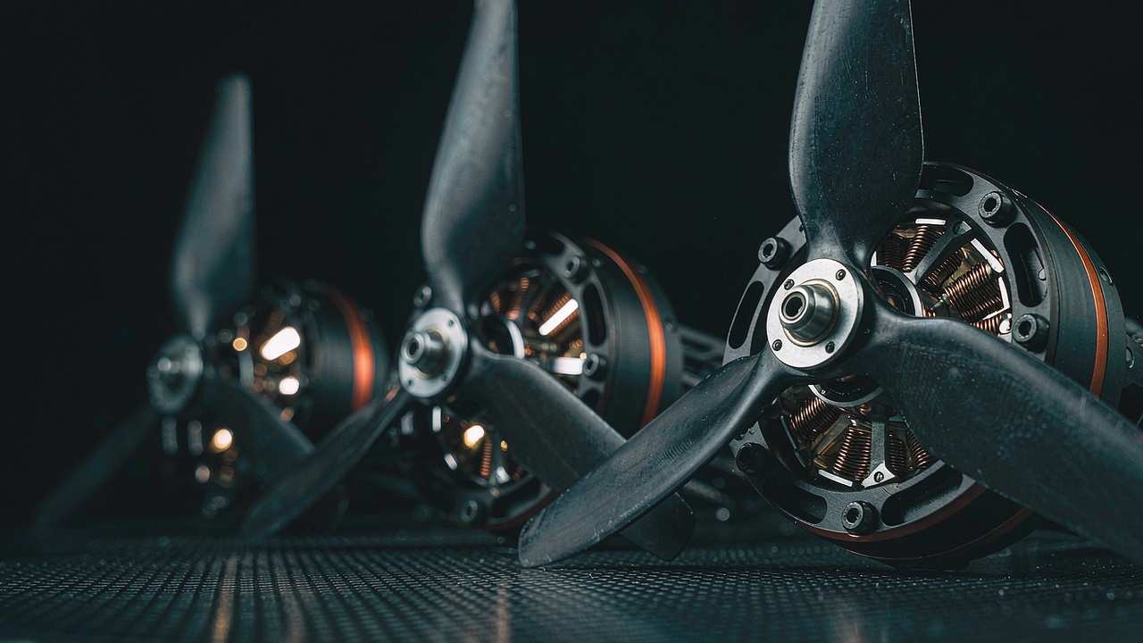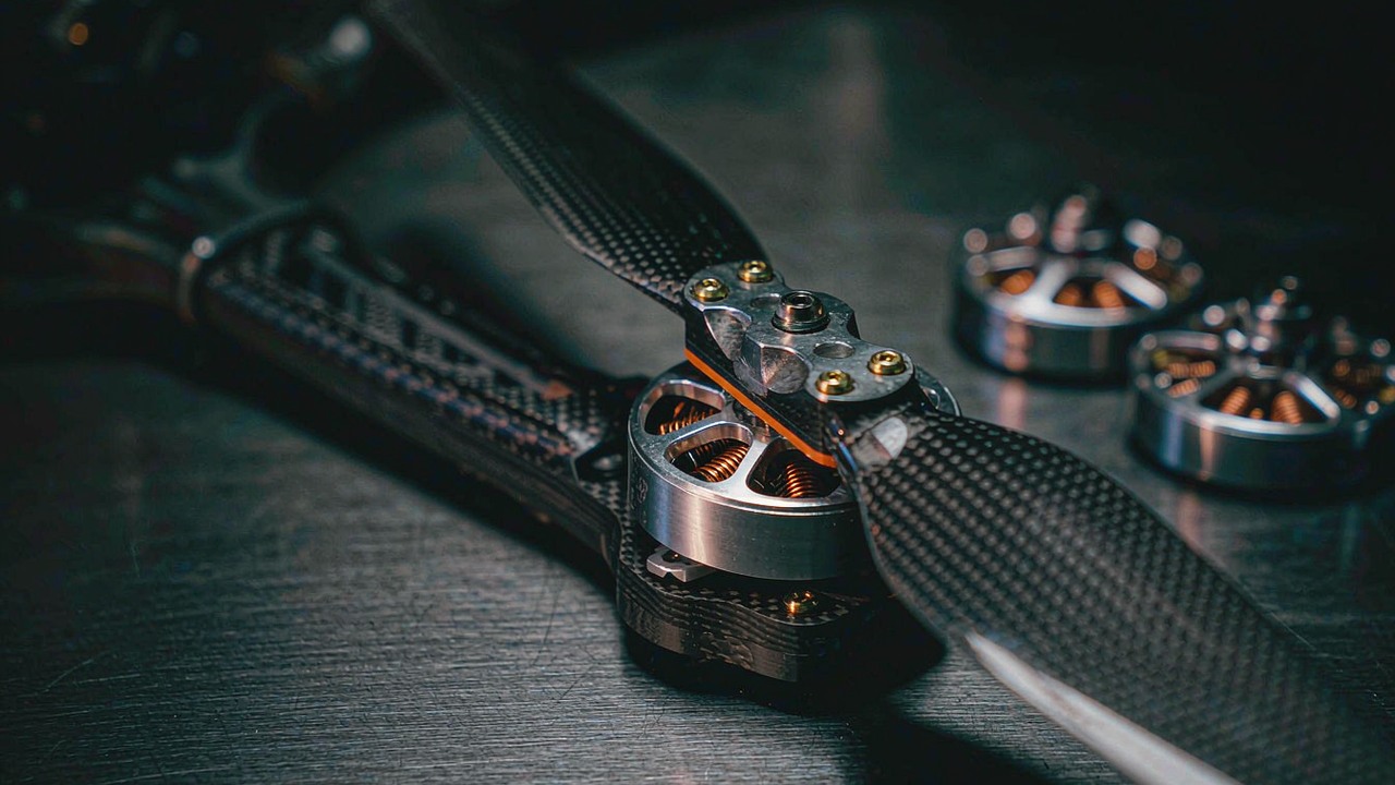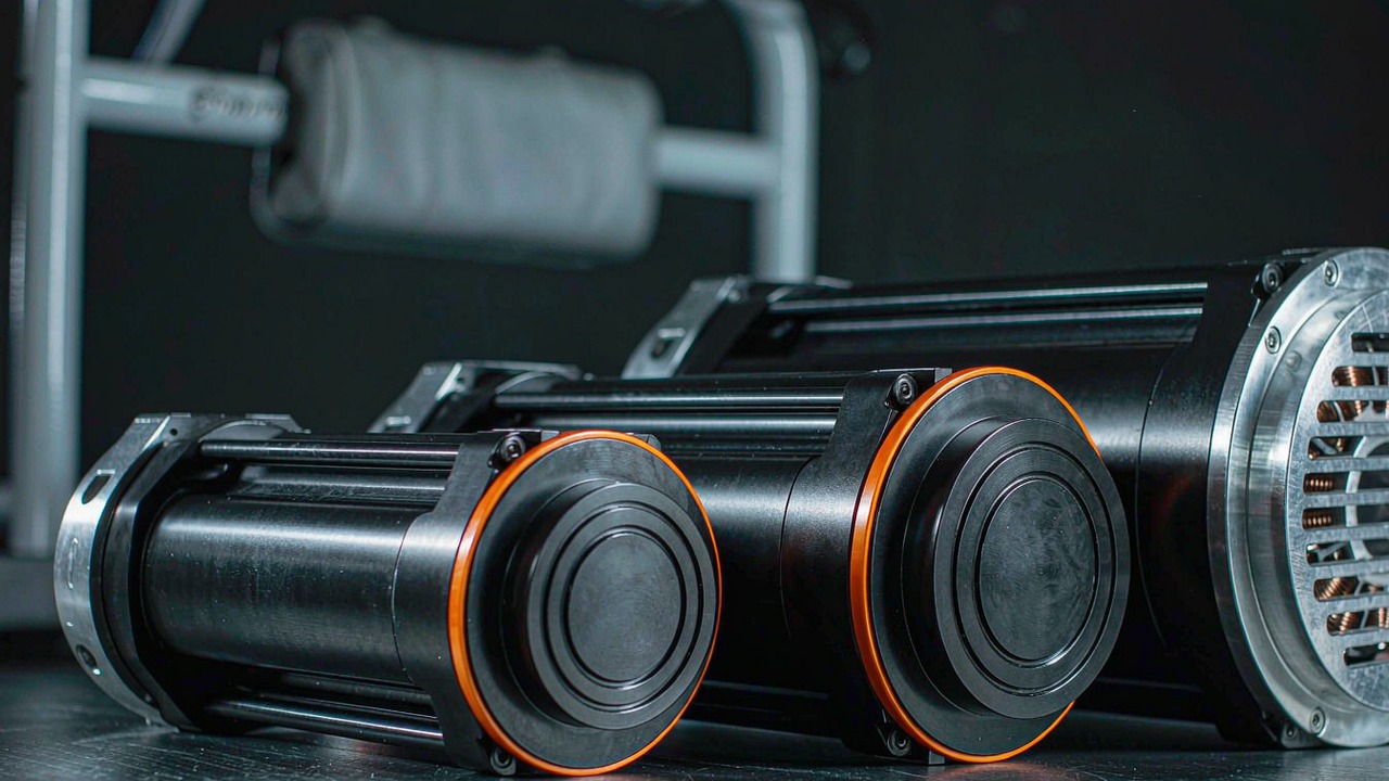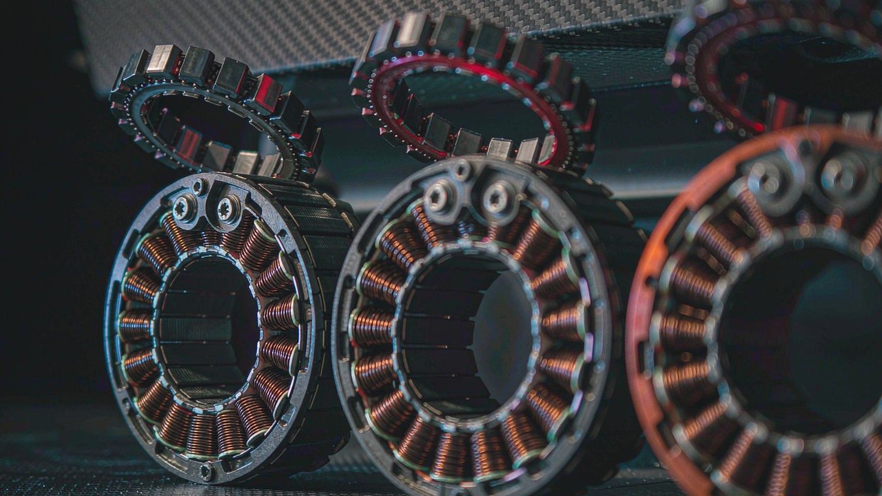

Sizing a motor for Manned Aircraft Propulsion Systems starts from a different premise than sizing one for an unmanned airframe. An unmanned aircraft can be designed around a mission and a cost, and for a great many missions it is reasonable to let a propulsion failure end the flight. An aircraft carrying a person cannot be designed that way. The duty is longer, the operating point sits further towards the continuous end of the envelope, a single failure has to be survivable rather than merely unlikely, and every figure the integrator depends on has to be traceable to a test rather than to a headline. This guide works through three T-Motor U15 motors - a 1740 g unit with the widest recorded bus window, a 4408 g unit built for a 24 S bus, and a 5130 g unit that records the highest thrust of the three - and explains which recorded value settles the choice in each case, and which values sit with the manufacturer's datasheet.
All three are outrunner brushless motors driven by an external ESC, and all three sit in a single ToBMS category, UAV Motors. What separates them is mass, KV, recorded thrust and the bus each one is built for, and those differences map onto light two-seat airframes, powered paraglider trikes and the larger cargo platforms being adapted for crewed operation. Every figure quoted here comes from the corresponding ToBMS product record; conversions between grams and kilograms, ratios built from two recorded values, and any quantity inferred from cell chemistry are labelled as derived, and a field carrying no value is marked as missing rather than filled in from a neighbouring model. Two of the three records do not carry the electrical columns in full, and knowing which column is missing from which record is part of making the choice.
Quick answer
The first decision in this category is not thrust, it is how many motors the airframe carries and what happens when one of them stops. Everything else - KV, mass, bus, propeller - is then sized against that failure case rather than against a nominal hover point. On that basis the three motors here occupy three distinct roles rather than forming a ranking.
Where the airframe is small, the pack is the binding constraint and the propulsion layout has enough units that losing one leaves a comfortable margin, the U15 II KV80 is the only one of the three that accepts 12-24S, and at 1740 g it is the lightest by a factor of more than two. It records 36.5 kg of maximum thrust and 8580 W across a 180 s window, and it is the only one of the three whose record publishes any power figure at all.
Where the airframe is a fixed 24 S design and the mass budget allows a heavier motor, the U15XL KV38 records 81.2 kg of thrust at 4408 g, with a 180 A peak current figure, a 3.5 A idle current at 10 V and a 17 mΩ winding - the lowest resistance recorded in this group, tied with the U15 II - which makes it the unit whose electrical record is most complete through the middle of the mass range.
Where the highest recorded thrust per motor is what the design needs, the U15XXL KV29 records 101.4 kg at 5130 g on the same 24 S bus and the same 36N42P stator, with a 210 A peak current figure and 20 mΩ of winding resistance. What none of the three records carries is a continuous, indefinite power rating. The nearest available substitutes are the 180 s power figure on the U15 II and the peak current figures on the other two, and those are duty-window statements rather than continuous ratings - a distinction worth holding onto when a design review asks how long a climb can be held.
What changes when the aircraft carries a person
Nothing about the construction of these motors separates them from any other large outrunner in the category. What changes is the shape of the requirement, and in Manned Aircraft Propulsion Systems the requirement decides which column of the record becomes binding.
Failures have to be survivable, not merely unlikely
An unmanned airframe can be designed so that a propulsion failure ends the mission, and at that scale the trade is usually acceptable. A crewed airframe cannot: the propulsion layout has to be able to lose at least one unit and still hold the aircraft up, which moves the useful figure from thrust per motor to thrust per motor with the worst one removed. On a four-motor layout three quarters of the installed thrust remains; on a six-motor layout, five sixths. The arithmetic is simple, and it is why a motor that looks oversized against a nominal hover point is frequently correctly sized against the failure case instead.
Read against this group, a four-motor airframe built on U15XXL KV29 motors would have three units left after a single failure, holding about 304 kg of the 406 kg all four record together - both figures derived from the recorded 101.4 kg per motor. The same arithmetic on U15 II KV80 leaves 110 kg of the 146 kg that four of them record. Neither number decides whether an airframe flies on three motors; that depends on the design, and the design belongs to the integrator rather than to the motor. What the numbers do show is which motor buys the larger margin for the mass it adds, and where a design sits close to its margin, that difference is the whole selection argument.
The sustained operating point matters more than the peak
A hover in a crewed aircraft is not a transient, and neither is a cruise climb. Where an unmanned mission profile spends its time in brief excursions above a comfortable average, a crewed profile tends to hold a high fraction of available power for minutes at a time - which puts thermal behaviour rather than peak output at the centre of the decision. Peak figures still matter, but for a different purpose: they size the harness, the connector and the ESC, because it is current, not power, that a conductor feels.
The columns that speak to sustained operation are the ones most likely to be absent. The U15 II KV80 record carries 8580 W for a 180 s window, which is a duty statement rather than a rating, and neither of the other two records carries a power figure at all. On those two, the electrical information available is a peak current value - 180 A on U15XL KV38 and 210 A on U15XXL KV29 - alongside a no-load idle current measured at 10 V. That is enough to size a harness and to compare windings; it is not enough to declare a continuous operating point, and treating it as though it were is the single most common way a crewed propulsion estimate goes wrong.
Mass at the propeller end is charged twice
Motor mass on an aircraft is not only lifted, it is accelerated. On a wing or an arm, rotating and non-rotating mass at the outboard end raises the inertia the airframe has to overcome in pitch and roll, which shows up as control response and ride quality rather than as a thrust deficit. The effect is felt continuously, while the thrust bought with that mass is only used at the top of the envelope.
The spread across this group is large enough to matter. Four U15 II KV80 motors total 7.0 kg, four U15XL KV38 units total 17.6 kg and four U15XXL KV29 units total 20.5 kg - all derived from the recorded masses. The gap between the lightest and the heaviest four-motor set is therefore 13.6 kg of airframe, which on a light two-seat platform is a real number rather than a rounding error. It is also the reason the lightest unit here is not automatically the right starting point: it records the least thrust of the three, and a design that needs the thrust cannot buy it back by shaving mass anywhere else.
Recorded data is a design input, not a summary
In an unmanned project a missing specification column is an inconvenience that can be resolved by testing. In a crewed project it is an open action in a design review, because the numbers that close a review have to come from a documented test rather than from an inference. That changes how a record with a missing column should be read: not as a gap to be filled with a plausible value borrowed from a similar motor, but as a question to put to the manufacturer before the part is selected.
Applied here, the U15 II KV80 record documents power and dimensions, with peak and idle current held on the manufacturer's datasheet; the U15XL KV38 and U15XXL KV29 records document peak and idle current, resistance, shaft and lead, with the power figure held on the manufacturer's datasheet. Each of the three therefore carries what one kind of integration needs and leaves a column open for another, and the honest response is to name the gap rather than paper over it. It is worth noting that the manufacturer's own naming for two of these units points directly at crewed operation, so a design review can read that naming alongside the recorded thrust and current figures.
The numbers that decide the pick
Six groups of values carry nearly all of the decision in manned aircraft propulsion systems work. Three of them are published for all three motors and three are not, which is worth establishing before a shortlist is drawn up.
Lift with one motor removed
This is the filter that removes candidates rather than ranking them, and it works in the opposite direction from a conventional thrust comparison. A motor is eliminated here for a reason that has nothing to do with its own rating: the thrust its siblings can produce after its own failure is insufficient, so the question is always asked about the set rather than about the individual. Across this group the recorded maximum thrust runs from 36.5 kg to 101.4 kg, and the three-quarter figure that a four-motor layout would retain runs from 110 kg to 304 kg - derived throughout from the recorded per-motor values.
Two cautions belong with that arithmetic. First, maximum thrust is recorded by ToBMS as a single figure taken from the manufacturer's test data, describing one propeller at one throttle setting and one voltage; it is a ceiling rather than a working point. Second, none of the three records a hover-rated thrust value, so a margin computed from the maximum figure is a margin against a ceiling, and the real hover margin is smaller by whatever gap separates the two. Where a design sits close to the line, that gap is worth closing from the manufacturer's test data before the airframe layout is fixed.
What the records say about continuous operation
The only sustained figure in this group is the U15 II KV80's 8580 W for a 180 s window. Read as a duty statement it says the unit held that power for three minutes on a test stand, which is a useful indication of thermal capability and not a definition of what can be held indefinitely. One derived check is available: if 8580 W were drawn at the top of its 12-24S window, a 24 S pack at roughly 88.8 V nominal - the standard 3.7 V per cell convention rather than a motor specification - implies about 97 A by our estimate, a figure derived from the recorded values rather than a manufacturer rating. That says more about how the test was run than about the motor's limit.
The other two motors publish no power figure, so their sustained behaviour has to be inferred from the current and resistance columns. That inference is legitimate and it is limited: copper loss scales with the square of current, so the numbers below are useful for comparison and useless as a rating. What they do establish is which of the two heavier motors runs cooler at its own peak, and that is a fair thing to compare between two records of the same kind.
Bus, current and the harness behind them
Bus voltage is set by the pack, and in this group it largely sets the candidate list. The U15 II KV80 accepts 12-24S, which is the widest recorded window of the three and the only one that brackets a lower-voltage pack; the U15XL KV38 and U15XXL KV29 both record 24 S. A wider window is not automatically better - it means the same motor can be run on a milder pack, which is useful where one airframe has to serve a test programme and a flight programme without a motor change.
Current is where the heavier two separate from the lightest. The U15XL KV38 records 180 A peak and the U15XXL KV29 records 210 A peak, while the U15 II KV80 publishes no peak current figure, so no like-for-like comparison across all three is available. On the 24 S convention of roughly 88.8 V nominal, a 210 A peak on the U15XXL implies about 18.6 kW at that instant and a 180 A peak on the U15XL about 16 kW by our estimate - both figures derived from the recorded values rather than manufacturer ratings, and both useful mainly for sizing. The same numbers set the copper cross-section in the leads, the connector rating and the ESC's continuous current, and on a crewed aircraft those three items are usually selected with less margin than the motor itself is.
Winding resistance and where the heat goes
Resistance is the column that links current to temperature. At a given current it fixes the copper loss, and copper loss is heat generated inside a motor that is already relying on airflow for cooling. Two of the three records publish it: 17 mΩ on both the U15 II KV80 and the U15XL KV38, and 20 mΩ on the U15XXL KV29. Held at their respective recorded peak currents, the 17 mΩ winding of the U15XL KV38 dissipates about 551 W and the 20 mΩ winding of the U15XXL KV29 about 882 W - both our estimate from the recorded values and uncorrected for temperature, and both a peak-instant figure rather than a steady one, since a sustained climb draws far less than peak.
The comparison is instructive precisely because it does not favour the larger motor on every axis. The U15XXL KV29 has the higher resistance and the higher peak current, so it produces more heat at peak than the U15XL KV38 does; in exchange it records 101.4 kg of thrust against 81.2 kg. Choosing between the two on a crewed airframe is therefore a question about the duty profile - how long the high-power segment lasts, and how much airflow is available during it - rather than a question about which motor is better. The U15 II KV80 cannot be placed on this axis at all, since its peak current is not recorded; its 17 mΩ winding is the lowest here, which is consistent with a smaller stator carrying fewer turns.
Rotor geometry and the propeller it can turn
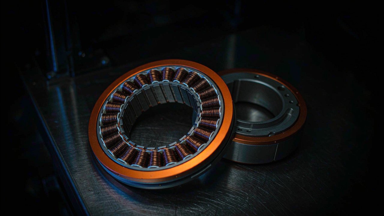
All three records share the same 36N42P stator configuration, which is common to the whole group and useful for selection: it means the differences between them are in winding, magnet, stack and mass rather than in slot-and-pole architecture. That removes one variable from the comparison and leaves propeller matching as the remaining geometric question.
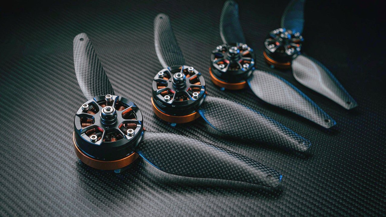
KV is the value that decides which propeller a unit can turn at a useful speed. The three values here - 80, 38 and 29 - are not a strength ranking; they are three answers to the question of where the rotor speed should land for a given bus. A 29 KV unit on a 24 S bus turns a much larger propeller at a lower speed than an 80 KV unit does, which is why the two are not interchangeable even where the airframe could physically accept either. Where a design is scaling an existing airframe up or down, matching the KV and the propeller disc together is what preserves the operating point, and changing only the motor size is what breaks it.
Shaft, mounting and lead interface
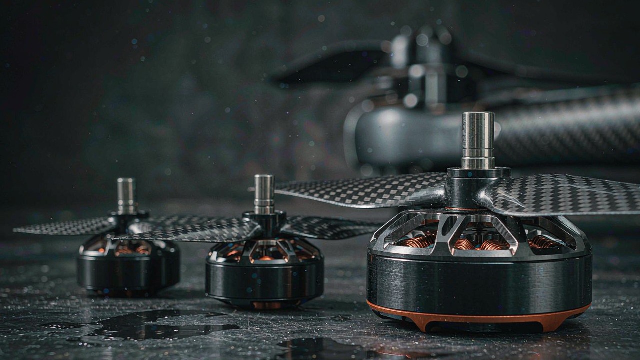
The mechanical columns decide whether a motor can be installed, and on a crewed aircraft they also decide how serviceable it is. The envelope is close across the group but not identical: the U15 II KV80 measures Ø147.5 × 55 mm, while the U15XL KV38 and U15XXL KV29 both measure Ø151.5 mm and differ in length at 96 mm and 106 mm respectively. The 55 mm length of the lightest unit is a little over half that of the largest, which is where most of its 3.39 kg mass advantage over the U15XXL KV29 comes from.
Shaft diameter splits the group in a way that matters more than it looks: the U15 II KV80 records a 20 mm shaft where the other two record 25 mm, which changes the propeller adaptor, the retention method and the load a hub can carry. The U15XL KV38 and U15XXL KV29 each publish a 200 mm lead length, which is enough to reach an ESC mounted away from the arm end and to keep the high-current run short; the U15 II KV80 records a 100 mm cable length instead, which suits a closer ESC but is not the same measurement on the same basis, so the two should not be compared as though they were. Where a value is not recorded, the assumption should be checked against the part rather than against a sibling model.
Three T-Motor U15 motors compared
The table below collects the three units in ascending mass order. Every value is as published in each ToBMS product record, and gaps are marked rather than filled.
| Model | Weight | Maximum Thrust | Stator | Peak Current | No. of Cells (LiPo) |
|---|---|---|---|---|---|
| T-Motor U15 II KV80 | 1740 g | 36.5 kg | 36N42P | Not listed | 12-24S |
| T-Motor U15XL KV38 | 4408 g | 81.2 kg | 36N42P | 180 A | 24S |
| T-Motor U15XXL KV29 | 5130 g | 101.4 kg | 36N42P | 210 A | 24S |
All three motors are recorded in the ToBMS UAV Motors category and are published by T-Motor. Thrust is stored in grams in each record and shown here converted to kilograms; the thrust, mass and current figures are as recorded, and every ratio or total quoted elsewhere in this article is derived from them and identified as derived where it appears. One cell in the table is marked rather than filled: no peak current is recorded for the U15 II KV80. Two further figures sit outside the table because no such column is carried at all - the power figure for both the U15XL KV38 and the U15XXL KV29 sits with the manufacturer's datasheet - so the group as a whole has no electrical column that is populated for all three.
The first pattern the table shows is that thrust and mass scale together almost exactly, and that the scaling does not reward size. The three units span roughly 2.9 times in mass from 1740 g to 5130 g, and roughly 2.8 times in recorded thrust from 36.5 kg to 101.4 kg - both derived. Thrust per unit of motor mass comes out at about 21.0, 18.4 and 19.8 times for the U15 II KV80, U15XL KV38 and U15XXL KV29 respectively, all derived the same way. The lightest unit therefore records the highest ratio of the three and the middle unit the lowest, which is worth stating plainly because it runs against the expectation that the largest motor is the most efficient way to buy thrust.
The second pattern is in the column that is missing. The unit with the highest recorded thrust publishes no power figure, and the unit with the widest bus window publishes no peak current - so on the electrical side each record is populated exactly where the other is not. A design that needs a continuous power number and a peak current number for the same motor will not find both in this group, and the appropriate response is to take the question to the manufacturer rather than to interpolate between records.
The third pattern concerns the bus. Two units sit on a fixed 24 S bus and one brackets 12-24S, and the shared stator configuration across all three means that this difference is entirely in the winding rather than in the magnetics. That is a useful thing to know when a design changes its pack: on the two 24 S units the pack is part of the specification, whereas on the U15 II KV80 a lower-voltage pack is inside the recorded window and only the propeller has to be re-matched.
Reading each motor against a manned mission
Recorded numbers only become a decision once they are read against what the aircraft does. Each of the three below suits a different kind of airframe, and none of them suits all three.
U15 II KV80 - the lightest unit and the widest bus
The U15 II KV80 records 1740 g, 36.5 kg of maximum thrust, an 80 KV winding, a 36N42P stator, 17 mΩ of resistance, a 20 mm shaft, a 100 mm cable length and a 12-24S window, with 8580 W recorded across a 180 s window. It is the only unit here that publishes a power figure and the only one whose bus window brackets a lower cell count, and at 1740 g it is less than half the mass of either of the others - the 55 mm body length against 96 mm and 106 mm is most of the explanation.
What that combination points at is a design where mass and pack flexibility carry more weight than peak thrust per motor. A four-motor layout on this unit totals 7.0 kg of motors against 17.6 kg and 20.5 kg for the same layouts on the other two - derived from the recorded masses - and the 13.6 kg difference between the extremes is available for structure, batteries or payload instead. On a light airframe with enough motors to absorb a single failure, that is a straightforward gain.
What it costs is thrust per unit and electrical documentation. Its 36.5 kg is a little over a third of the U15XXL KV29's 101.4 kg, so a four-motor layout on U15 II KV80 motors retains about 110 kg after a single failure against roughly 304 kg on the larger units - both derived. And with no peak current recorded, neither the harness sizing nor the copper-loss comparison can be closed from the record alone, which in a crewed project is an action item rather than a footnote.
U15XL KV38 - the middle mass point with the most complete electrical record
The U15XL KV38 records 4408 g, 81.2 kg of maximum thrust, a 38 KV winding on the same 36N42P stator, 17 mΩ of resistance, a 180 A peak current, a 3.5 A idle current at 10 V, a 25 mm shaft, a 200 mm lead length and a fixed 24 S bus. It is the only one of the three whose electrical record carries both a peak current and a resistance figure alongside an idle current measurement, which makes it the unit that can be placed on a thermal axis without going back to the manufacturer.
Its position in the group is the reason it is often the mid-range answer rather than a compromise. It shares the lowest recorded resistance of the three with the U15 II KV80, so at a given current it generates less copper loss than the larger U15XXL KV29 does - about 551 W at its own 180 A peak against about 882 W at the other's 210 A peak, both derived - while recording 81.2 kg of thrust, which is more than twice the lightest unit's figure. A four-motor layout on these motors retains about 244 kg after a single failure, derived, and totals 17.6 kg of motors.
Its constraint is the bus. At a fixed 24 S there is no recorded option to run a milder pack without leaving the window, so an airframe that wants to begin flight testing on a lower cell count has to change motors or change its pack plan. The 200 mm leads and the 25 mm shaft, on the other hand, are the more generous of the two interface sets recorded here and suit an installation where the ESC sits inboard of the arm.
U15XXL KV29 - the highest recorded thrust of the three
The U15XXL KV29 records 5130 g, 101.4 kg of maximum thrust, a 29 KV winding on the 36N42P stator, 20 mΩ of resistance, a 210 A peak current, a 3.3 A idle current at 10 V, Ø151.5 × 106 mm, a 25 mm shaft, a 200 mm lead and a fixed 24 S bus. It is the heaviest and the highest-thrust unit in the group, and the manufacturer names it directly for crewed as well as unmanned aircraft - a naming that the recorded thrust and current figures bear out, with the sustained power figure held on the manufacturer's datasheet.
Read as a set, this is the unit that buys margin. A four-motor layout retains about 304 kg after a single failure on the recorded figures, derived, and a six-motor layout retains five sixths of 608 kg. Against that, four of them add 20.5 kg of motor mass, and at peak current each one produces roughly 882 W of copper loss in a 5130 g package - our estimate from the recorded values, uncorrected for temperature - which in a sustained climb is the number that decides whether the cooling path is adequate. The 20 mΩ winding is the highest resistance recorded here, and because copper loss scales with the square of current, the combination of the highest current and the highest resistance in the same unit is exactly what puts thermal design at the centre of an installation built on it.
The 3.3 A idle current at 10 V, marginally below the U15XL KV38's 3.5 A, is consistent with a lower-KV winding drawing slightly less current to spin itself, and it is the only comparative signal available between the two on the no-load side. On its own it is not enough to draw a conclusion about efficiency across the operating range, and it should not be used as one.
Where these systems are used
The same three motors appear in airframes whose constraints differ enough that the selection argument changes shape between them, which is why the platform matters as much as the record in manned aircraft propulsion.
Light two-seat and personal eVTOL platforms
These are the designs where the failure case drives everything, because the propulsion layout is usually the only system that can hold the aircraft up. A distributed layout with six or eight motors is common, precisely because it converts a single failure into a partial loss of thrust rather than a total one, and that layout preference is what makes a lower-thrust, lower-mass motor viable against a higher-thrust alternative. The relevant records here are the ones that publish enough electrical information to size a harness - which favours the U15XL KV38 and U15XXL KV29 - and where the design is still iterating on pack voltage, the U15 II KV80's 12-24S window is the only recorded flexibility in the group. The VTOL Drone grouping covers the same lift-and-cruise compromise from the unmanned side, where the constraint set is different.
Powered paragliders and paramotor trikes
This class of airframe is the closest thing in the category to a flying machine built around a single propulsion unit, and it is also where mass tells most directly. A paramotor trike carries one or two motors on a structure whose mass budget is tight and whose propeller is large and slow-turning, which points at a low KV and a light unit rather than at maximum thrust. The 29-to-80 KV spread across the group is not the whole story here - the meaningful comparison is against the other two units at 38 and 29 KV - but at 1740 g with a wide bus window the U15 II KV80 suits an airframe where the pack is chosen for endurance rather than for voltage. The trade, on a single-motor installation, is that there is no second unit to absorb a failure, and a design in that position is making a different kind of decision altogether.
Cargo airframes crossing into crewed roles
A number of large multirotor platforms are developed first for freight and then adapted to carry a person, and the propulsion set is usually the part that carries over unchanged. In that case the useful reading of these records is the failure-case arithmetic rather than the nominal thrust: a layout already sized on U15XXL KV29 motors around a freight payload retains about three quarters of its installed thrust after one failure, derived, which is the margin a crewed variant would be assessed against rather than a demonstrated capability. This is also the setting where the missing continuous power figure hurts most, because the crewed duty profile is longer than the freight one and the thermal margin that was adequate for a short cargo hop may not be adequate for a longer crewed leg. The Heavy Lift Drone application groups the same motors around payload classes rather than around the failure case, and the two views are worth reading together.
Where the same motors stop being the answer
There is a boundary in this category and it is worth naming. The moment a design moves from holding an altitude to covering a distance efficiently - from hover to cruise - the entire ranking above stops applying, because the operating point moves to the region where a low-KV winding, a low winding resistance and a large slow propeller win on endurance rather than on thrust. That is a different selection problem, collected under Long Endurance UAV rather than here. Similarly, an airframe whose propulsion set is expected to hold a sustained power figure as a certification input rather than as a performance target is asking a question that none of these three records answers, and the answer has to come from the manufacturer's test documentation.
Selection checklist
Three checks cover most of the ground, and they work better in this order because each one narrows the field for the next.
Duty first
Fix what the aircraft is asked to do before comparing motors: how long the high-power segments last, whether the layout holds altitude in a hover or only in forward flight, and whether the pack voltage is already decided. On a crewed airframe those three answers usually eliminate more candidates than any specification column, because they decide whether a sustained figure is needed at all and whether a recorded peak current is enough.
Redundancy second
Decide how many propulsion units the airframe carries and compute the retained thrust for the worst single failure, using the recorded per-motor figure and marking it derived. Compare that retained figure against the all-up mass with margin for control authority rather than just for lift, and remember that the recorded thrust is a ceiling from a test-stand value rather than a hover rating - none of the three records here publishes a hover-rated value, so the working margin is smaller than the ceiling margin by that gap.
Interfaces and open questions last
Only once duty and redundancy are fixed do the mechanical and electrical columns decide between the survivors. Check shaft diameter, mounting pattern, lead and cable lengths against where the ESC will sit, size the harness against the recorded peak current rather than against the power figure, and write down which columns the record does not carry so they can be closed from the manufacturer's test data before the part is committed.
- Fix the duty profile and the pack voltage first, and treat a design that has not decided either as not yet ready to shortlist motors.
- Compute retained thrust for the worst single failure on the recorded per-motor figure, and label the result as derived.
- Compare retained thrust against all-up mass with margin for control authority, remembering that recorded maximum thrust is a ceiling rather than a hover rating.
- Check whether the record carries a sustained power figure at all, and do not treat a peak current value as a substitute for one.
- Size leads, connectors and the ESC against recorded peak current, and check copper loss at that current against the cooling path available.
- Prefer a bus window that brackets the packs actually available where the design is still iterating, and treat a fixed cell count as a specification to be designed around.
- Check shaft diameter, mounting pattern and lead length against the ESC location, and do not compare a cable length against a lead length as though they were the same measurement.
- Record every column the product record leaves empty, so the manufacturer's test documentation can close them before selection is committed.
Frequently asked questions
QWhat makes a motor suitable for manned aircraft propulsion rather than for a large unmanned airframe?
The motor is not built differently; the requirement is. A crewed airframe has to keep flying after a propulsion failure, so the layout is sized on retained thrust rather than on nominal thrust, and the operating point sits closer to the continuous end of the thermal envelope than an unmanned mission profile does. Both of those move the useful specification towards sustained behaviour and away from peak figures - which is exactly the direction in which the records for these three motors are least complete.
QDo these motors hold a certified continuous power rating?
No such rating appears in any of the three ToBMS records, and certification of an aircraft is the integrator's process rather than a property of a motor. The only sustained figure recorded here is the U15 II KV80's 8580 W across a 180 s window, which is a duty statement rather than an indefinite rating. The other two records publish no power figure at all, only a peak current - 180 A on the U15XL KV38 and 210 A on the U15XXL KV29. Where a design needs a continuous rating, that document has to come from the manufacturer.
QWhich of the three gives the most thrust for its own mass?
On the recorded figures the U15 II KV80 does, at roughly 21.0 times its own mass, derived from 36.5 kg of thrust and 1740 g. The U15XXL KV29 follows at roughly 19.8, also derived, and the U15XL KV38 at roughly 18.4. The ordering is worth noting because it disagrees with the assumption that the largest motor is the most efficient way to buy thrust: the heaviest unit here records the highest absolute thrust but not the highest ratio, and a design that needs absolute thrust has no way to substitute ratio for it.
QHow much thrust is left after one motor fails?
On a four-motor layout, three quarters of the installed thrust; on a six-motor layout, five sixths. Applied to this group, four U15XXL KV29 motors record 406 kg together and would retain about 304 kg, and four U15 II KV80 motors record 146 kg and would retain about 110 kg - both derived from the recorded per-motor figures. Whether the aircraft flies on the retained figure depends on the airframe and the flight condition, which is the integrator's analysis rather than something a product record can answer.
QIs the widest bus window the best choice?
Not on its own. The U15 II KV80 is the only unit here that records 12-24S, which is genuinely useful where the pack voltage is still being decided or where one airframe has to serve two programmes. But a wide window comes with the lowest recorded thrust of the three, so it is a flexibility-versus-capability trade rather than a free option. Where the pack is already fixed at 24 S and a higher thrust per motor is needed, the narrower records belong to the more suitable motors.
QWhy does the comparison table say "Not listed" for one cell?
Because no peak current value is carried for the U15 II KV80, and filling that cell from the U15XL KV38 or U15XXL KV29 record would be exactly the kind of inference that produces a wrong installation. Two consequences are worth naming: the harness cannot be sized from the record, and the copper-loss comparison between the three cannot be completed, since loss scales with the square of a current that sits with the manufacturer's datasheet.
QDo all three motors use the same stator?
Yes. All three records carry a 36N42P configuration, which means the differences between them sit in the winding, the magnet, the stack and the mass rather than in the slot-and-pole architecture. That removes one variable from the comparison and leaves KV and the propeller it has to turn as the geometric question that decides where the operating point lands: 29 KV on 24 S and 80 KV on the same nominal bus are two answers to the same question, not a lower and a higher version of one answer.
Official resources
All three motors are published by T-Motor, and the manufacturer's own pages carry the test data and documentation that the ToBMS records do not reproduce: the U15 II KV80, the U15XL KV38 and the U15XXL KV29, with the wider range at the T-Motor official store. Where a ToBMS record is silent - the U15 II KV80's peak and idle current, the U15XL KV38 and U15XXL KV29 power figures, and any hover-rated thrust value across all three - those pages or the corresponding datasheet are where the gap has to be closed.
Where to go next
Reading this far produces a shortlist rather than a decision, and three tools turn that shortlist into one: every motor here sits in the UAV Motors category, candidates can be narrowed by KV, mass and bus in Select, and two or three units can be set against each other in Compare Products. The application side of the same decision is collected on the Manned Aircraft Propulsion Systems page, which groups the recorded matches by platform rather than by specification.
Two existing guides extend sideways from here. The heavy-lift drone motor guide covers two of these three motors from the payload-class side, where the thrust budget is the organising idea rather than the failure case, and is the counterpart to this crewed view. The UAV motor selection guide places these units among the wider T-Motor range where the questions change shape entirely, and the complete BLDC motor guide puts every class in one frame for anyone starting from the technology rather than from an airframe.
The short version: fix the duty profile and the pack before comparing motors, compute retained thrust for the worst single failure rather than nominal thrust, then choose between what is left on mass and on electrical documentation. On this group that sequence usually lands on the U15 II KV80 where mass and pack flexibility dominate, the U15XL KV38 where the electrical record has to be complete and the bus is already 24 S, and the U15XXL KV29 wherever the highest recorded thrust per motor is what the airframe actually needs.