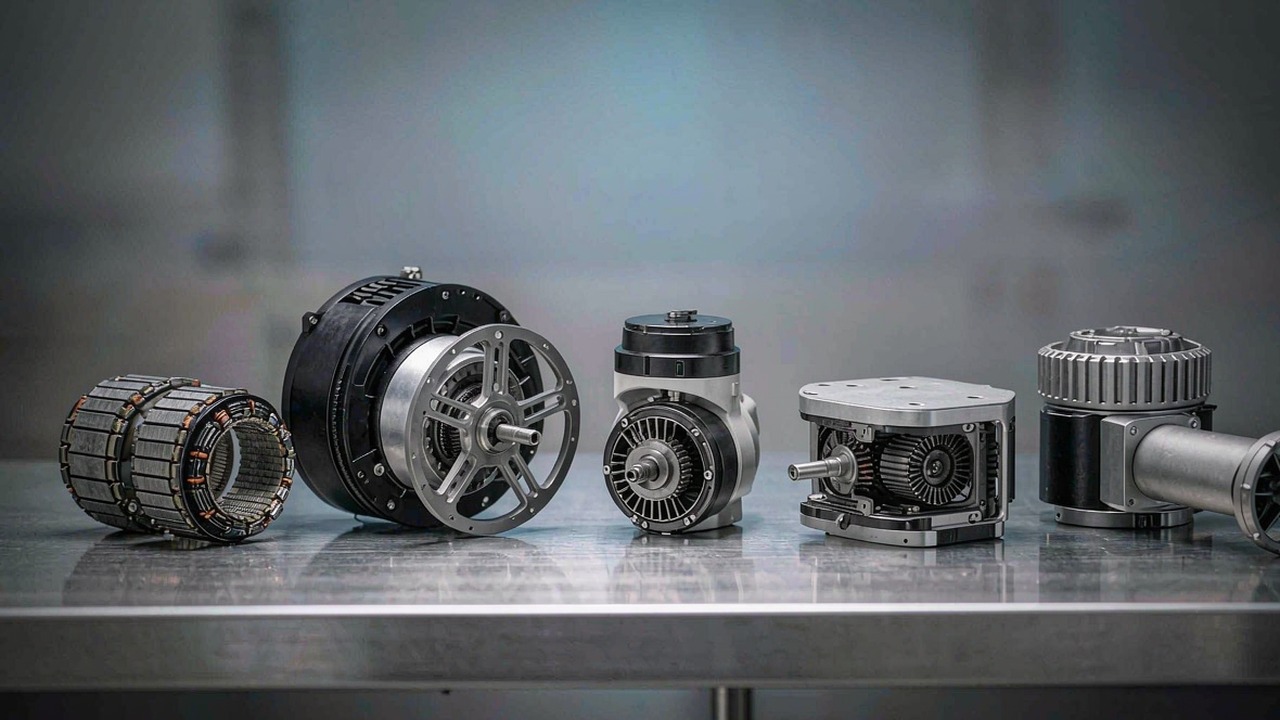
A BLDC motor is a brushless DC motor: a permanent-magnet rotor, a wound stator and an electronic controller that does the commutation the brushes used to do. That single change is why BLDC motors now sit inside robot joints, multirotor airframes, camera gimbals and subsea thrusters - there is no brush to wear, no commutator to arc, and the torque curve is predictable enough to be controlled in software. It is also why "BLDC motor" is no longer a single buying decision: the same electromagnetic principle is packaged seven different ways, and the packaging decides almost everything about how the motor is specified.
This guide explains how a brushless DC motor works, which specifications genuinely change a decision, and how the seven motor categories on ToBMS differ. Each category gets the same three questions - what it is, what decides the pick, and where it fits - so the section can be read on its own or compared against the others. Every figure is taken from ToBMS product data or the manufacturer's published specification; nothing here is estimated.
Quick Answer
A BLDC motor replaces the mechanical commutator of a brushed motor with an electronic one, so the controller - not a brush - decides which stator coil is energised and when. The practical consequences are higher efficiency, a much longer service life, better torque per unit mass, and a torque-speed behaviour that a controller can shape in software. The cost is that a brushless DC motor is never a standalone part: it only works with a driver that knows, or can infer, rotor position.
Choosing one is a two-step problem. First pick the category that matches the mechanical job - a bare frameless kit if the machine structure should be the housing, an integrated actuator if the joint should arrive as a sealed module, a propulsion motor if the output is thrust rather than shaft torque, a direct-drive gimbal motor if the output is smooth low-speed motion, or a sealed thruster if the motor has to work underwater. Then, inside that category, size KV against the bus voltage and required speed, rated torque against the duty cycle, and peak torque against the transient case. Reading a specification without knowing which category it came from is the most common reason a shortlist goes wrong.
What a brushless DC motor is
The parts that replace the brushes
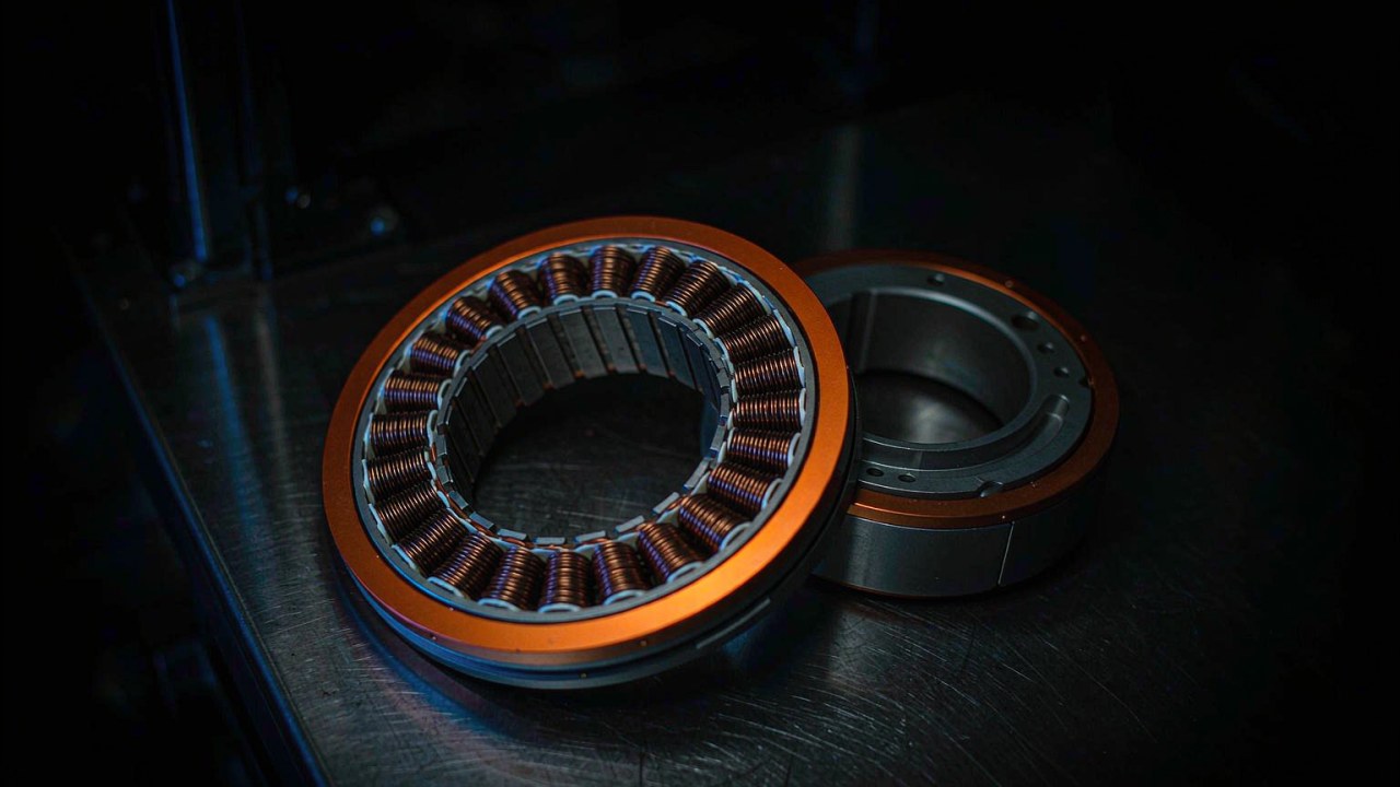
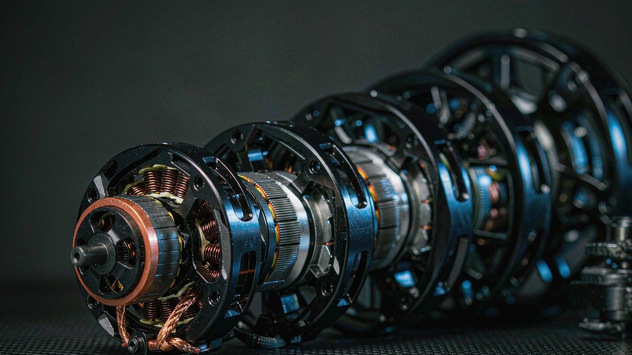
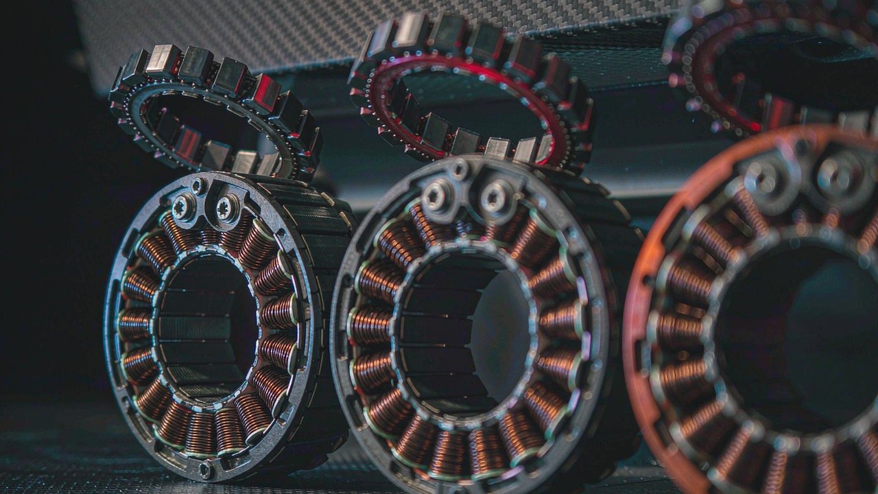
Every BLDC motor has the same three functional groups. The stator carries the windings - typically three phases in a slotted lamination stack - and stays still. The rotor carries permanent magnets, usually neodymium segments bonded or inset onto a steel hub. The controller energises the phases in sequence so the rotating stator field always leads the rotor field by the angle that produces maximum torque. In a brushed motor, a carbon brush and a segmented commutator perform that switching mechanically; in a brushless motor an inverter performs it electronically, thousands of times a second.
Two consequences follow directly. Because nothing rubs, the wear component of the maintenance budget effectively disappears, and the motor can be sealed - which is what makes underwater thrusters and IP-rated joint modules possible. And because the switching is under software control, torque is a commanded quantity rather than an emergent one, which is why the same hardware can be a stiff position servo in one application and a compliant force source in another.
Why the controller belongs in the conversation
A brushless DC motor has no meaningful specification without its driver. Commutation needs rotor position, and there are two ways to get it: measure it with sensors, or estimate it from the voltage and current the motor itself generates while spinning. Trapezoidal (six-step) drive is simple and adequate for propellers and pumps. Field-oriented control, or FOC, resolves current into torque-producing and field-producing components and holds them at the optimal angle, which is what gives smooth torque at low speed and high efficiency across the range - and what makes torque control, rather than just speed control, practical.
This is also why integrated robotic actuators are a category and not just a motor: the motor, the reducer, the encoder and the FOC driver are matched as a set, and the manufacturer publishes torque figures for that set rather than for the motor alone. Comparing those figures against a bare motor's means comparing different things.
Sensored, sensorless and what starts under load
Hall sensors give absolute commutation position from standstill, which matters whenever the motor must produce torque at zero or near-zero speed - a robot joint holding a pose, a gimbal resisting a gust, a thruster reversing direction. Sensorless control estimates position from back-EMF, which only exists once the motor is turning; it works well for propellers and fans, where the load is predictable and starting torque is low, and poorly for anything that must start against a load or reverse smoothly through zero. Many designs use an output-side encoder for control while the driver commutates on Hall sensors, which keeps the commutation robust and the control accurate at the same time.
Inrunner and outrunner
In an inrunner the rotor spins inside the stator; the magnets are close to the shaft, inertia is low, and the motor is easy to cool through the stationary outer housing. In an outrunner the rotor is a bell that rotates around the stator, so the magnets sit at a larger radius and produce more torque for the same magnetic loading - the geometry that dominates propulsion, where a propeller is bolted straight to the bell and no gearbox is needed. The frameless kits in the ToBMS Frameless Torque Motors category include both layouts, which is one reason their torque density figures are not directly comparable across families.
Specifications that decide the choice
KV, and why it is not a quality score
KV is the motor velocity constant: roughly the no-load rpm per volt applied. A 380 KV motor on a 22 V pack spins at about 8000 rpm unloaded; a 29 KV motor on the same pack reaches roughly 640 rpm. KV is set by the winding - more turns of thinner wire gives lower KV, more torque per amp and a lower top speed; fewer turns of thicker wire gives higher KV, more speed and less torque per amp. A higher KV is not a better KV. The right value is the one that puts the required speed at the available bus voltage while keeping current - and therefore heat - inside what the winding and driver can sustain.
Rated torque and peak torque
Rated torque is what the motor can produce continuously, within its thermal limits, in the mounting and cooling arrangement the manufacturer specified. Peak torque is a short-duration figure - a transient the motor can deliver for seconds, bounded by winding temperature, magnet temperature and driver current limit, not by a mechanical breaking point. Treating peak as a working number is the fastest route to a motor that quietly de-rates in service. The corollary matters just as much: a peak figure is not a statement about what the mechanics survive either. Gearbox shock limits, bearing loads and shaft strength are separate questions, and where they decide the design they need to be confirmed with the manufacturer.
Torque density in Nm/kg
Torque density is a comparison tool, not a specification - and it has to be stated twice, because rated and peak tell different stories. Dividing rated torque by mass says how much continuous output the mass budget buys, which is what a walking robot or a long-endurance airframe feels. Dividing peak torque by mass says how much transient capability is being carried, which matters for a leg that has to absorb a landing or an arm that has to break a stiction. In the frameless range the spread is wide: small inrunner kits and large outer-rotor standards land in different places on both measures, which is a design decision rather than a quality ranking. Where a range is quoted in Nm/kg on ToBMS, both numbers are listed so the comparison can be made on the one that matches the duty.
Gearing, back-driveability and backlash
A gearbox trades speed for torque and changes the character of the output at the same time. A high reduction ratio generally increases output torque and reduces back-driveability, because friction and reflected inertia are multiplied through the stage; a low ratio generally improves back-driveability and torque transparency, at the cost of the torque multiplication. Back-driveability is what lets a joint absorb an impact, be moved by hand during teaching, and estimate force from motor current instead of a load cell - which is the entire premise of the Quasi Direct Drive Actuators category at 8:1.
Backlash is the lost motion in the gear train, and it is worth asking about explicitly: it directly limits positioning repeatability and control stiffness. A number without its unit is not comparable, so confirm the figure against the manufacturer's datasheet before treating it as a design input.
Thermal limits and duty cycle
Heat, not torque, is what usually stops a motor. Copper loss scales with the square of current, so a duty cycle that doubles current quadruples that component of the loss; the rating reflects a specific mounting, a specific ambient and a specific duty. A frameless motor clamped into a large aluminium housing will hold much more than the same motor in free air, and a propulsion motor with prop wash over the bell will hold more than one on a bench. Where a figure has to be trusted, use the manufacturer's thermal conditions as the reference, not the headline number.
Voltage, current and the driver
Bus voltage sets the speed ceiling for a given KV; current sets the torque. The binding constraints are usually the driver's current limit and the insulation and connector ratings rather than the motor itself. Matching the three - pack voltage, KV and driver current - before comparing catalogues removes most of the false candidates early. It is also worth checking what the driver needs to know: a sensored motor that must hold torque at zero speed needs a controller that reads those sensors, and a FOC drive expecting an encoder will not accept a Hall-only interface.
Seven BLDC motor categories compared
The table below is the fastest way to find the right section of this guide. Torque and thrust figures are the published rated and peak values across each category currently listed on ToBMS; speeds are the KV range rather than a single number, because the output speed depends on the bus voltage chosen.
| Category | Built to do | Torque or thrust | Speed (KV) | Rated Voltage | Integrator supplies | Start here |
|---|---|---|---|---|---|---|
| Frameless Torque Motors | Stator-and-rotor kit built into the machine structure | 0.024-4 Nm rated, 0.072-12 Nm peak | 55-600 | 16-48 V | Housing, shaft, bearings, encoder | Robot joints |
| Robotic Actuators | Motor, reducer, encoder and drive in one sealed unit | 1.3-74 Nm rated, up to 222 Nm peak | 41-170 | 24-48 V | Mounting and bus only | Legged robots, arms |
| UAV Motors | Outrunner propulsion for airframes that must stay up | Thrust-rated, not torque-rated | 29-700 | 3-24S | Propeller, ESC, cooling | Multirotor, heavy lift |
| Drone Motors | FPV, racing, fixed-wing and VTOL propulsion | Thrust-rated, not torque-rated | 180-2150 | 2-12S | Propeller, ESC, frame | FPV, fixed wing, VTOL |
| Gimbal Motors | Smooth, silent, low-speed direct drive | 0.08-3 Nm rated, 0.28-7.7 Nm peak | 9.3-255 | 12-24 V | IMU and control loop | Camera stabilisation |
| Underwater Thrusters | Sealed, bidirectional subsea propulsion | 7-25 kgf mooring thrust | Not published | 36-48 V | Hull interface and cabling | ROV, AUV |
| Quasi Direct Drive Actuators | Low-ratio modules built for torque transparency | 5-55 Nm rated, 12.5-170 Nm peak | 30-80 | 24-48 V | Mounting and bus only | Force control, compliant joints |
Seven categories, each with its own output convention. Torque figures are manufacturer published rated and peak values; KV ranges are as listed across each category; thrust is the published maximum mooring thrust. Categories that publish thrust rather than torque are not inferior - they are answering a different question, and converting between the two requires the propeller and the operating point.
The first split is between categories that publish shaft torque and categories that publish thrust. Frameless motors, robotic actuators, gimbal motors and QDD modules are torque devices: the output is a shaft, and the load is defined in Nm. UAV motors, drone motors and underwater thrusters are thrust devices: the output is a fluid being moved, and the meaningful figure is thrust at a given propeller and voltage. Mixing the two in one comparison is the single most common specification error.
The second split is how much the buyer is expected to supply. A frameless kit assumes the machine structure provides the housing, the bearing arrangement and the thermal path, and it rewards that work with the lowest mass and the shortest axial length. An integrated actuator or thruster assumes the opposite: everything is matched and sealed, and the engineering effort moves to the software and the mount. Neither is more advanced; they suit different teams and different volumes.
Frameless torque motors
What it is
A frameless motor is a brushless DC motor sold as two parts - a wound stator and a magnet-carrying rotor - with no housing, no shaft, no bearings and no end caps. The machine builder supplies those. Because the motor has no envelope of its own, it can be built into the joint as structure, which removes the mass and length of a housing and lets the bearing arrangement be designed around the kinematics.
What decides the pick
Envelope first: the stator has to fit the available diameter and stack length, and that constraint eliminates more candidates than torque does. Then KV against bus voltage and required speed, then rated torque against the duty cycle, then peak against the transient case. Because the housing is the customer's, the thermal path is a design variable - the same stator holds substantially more continuous torque clamped into a large aluminium joint than it does in free air. Feedback is the remaining fork: Hall sensors for commutation, an output-side encoder for control, or both.
Where it fits
Frameless kits are the default for joint modules where mass and axial length are contested, for humanoid robots and quadrupeds where every gram sits at the end of a lever, and for exoskeletons and Rehabilitation Robot where the motor has to disappear into the mechanism. The range runs from the RI20 KV600 at 20 g and 0.024 Nm rated to the RO100 KV55 Standard at 710 g and 4 Nm rated, with the RO60 KV115 covering the middle. The full selection logic is in the frameless torque motor guide.
The manufacturer runs the 40 g kit in a joint assembly, which shows how much of the finished mechanism is structure the builder supplies rather than motor.
ToBMS video pageWatch on YouTubeRobotic actuators
What it is
An integrated robotic actuator is a BLDC motor, a planetary reducer, an output bearing, position sensing and an FOC driver in one bolt-on unit. The manufacturer matches the motor to the reducer and publishes torque at the output flange, so the buyer specifies the joint rather than the motor.
What decides the pick
Reduction ratio is the first decision, because it sets both the output torque and the character of the joint. Low ratios such as 6:1 and 8:1 favour speed, back-driveability and torque transparency; high ratios such as 64:1 multiply torque and generally make the output harder to back-drive, which suits load-holding joints. Hollow shafts matter when harnesses must pass through the joint - the AKH70-48 pairs a 48:1 stage with a cable route at 74 Nm rated. Backlash should be confirmed with its unit, since the measurement condition behind the recorded values is not stated.
Where it fits
Integrated modules suit teams that would rather spend engineering time on control than on bearing preload - collaborative robot arms, quadruped legs, Wheel Robot and AGVs. The category spans the AK40-10 V3.0 at 190 g and 1.3 Nm rated through to 74 Nm rated at 1396 g, with 6:1 to 64:1 stages in between.
The manufacturer walks through AK40-10, AK45-10 and AK45-36 together, which is the clearest illustration of how ratio and mass are traded inside one family.
ToBMS video pageWatch on YouTubeUAV motors
What it is
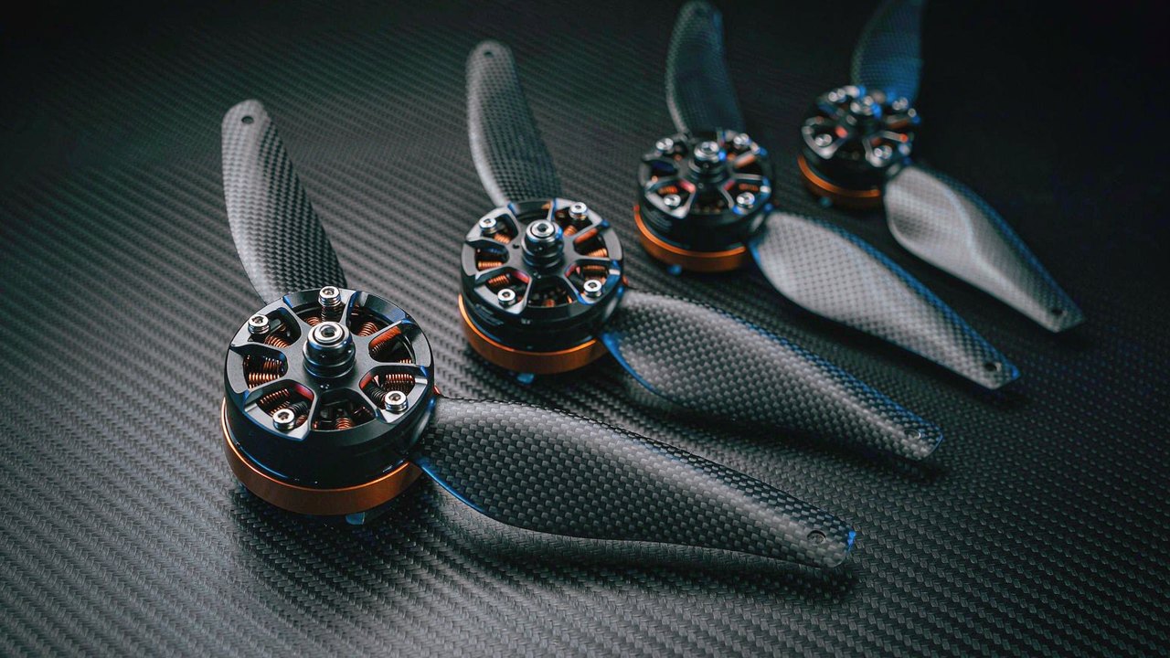
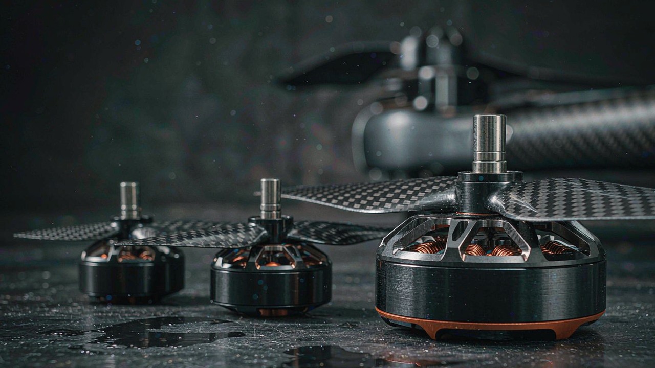
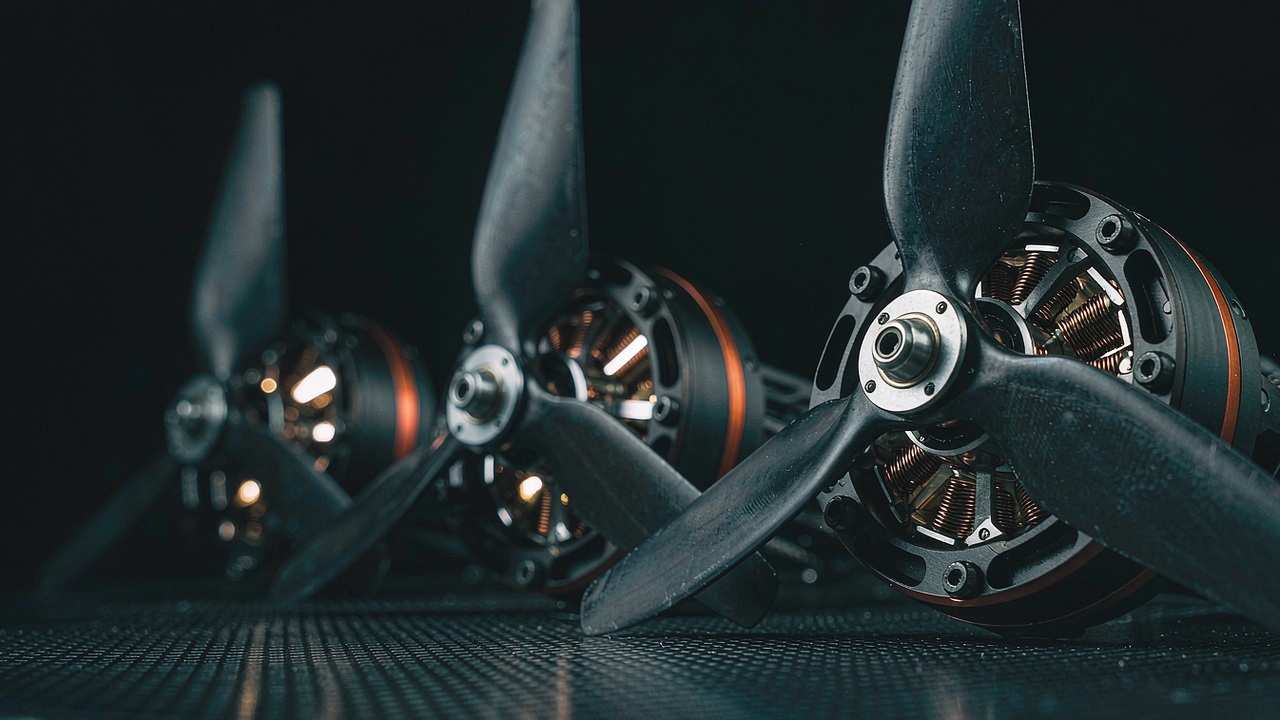
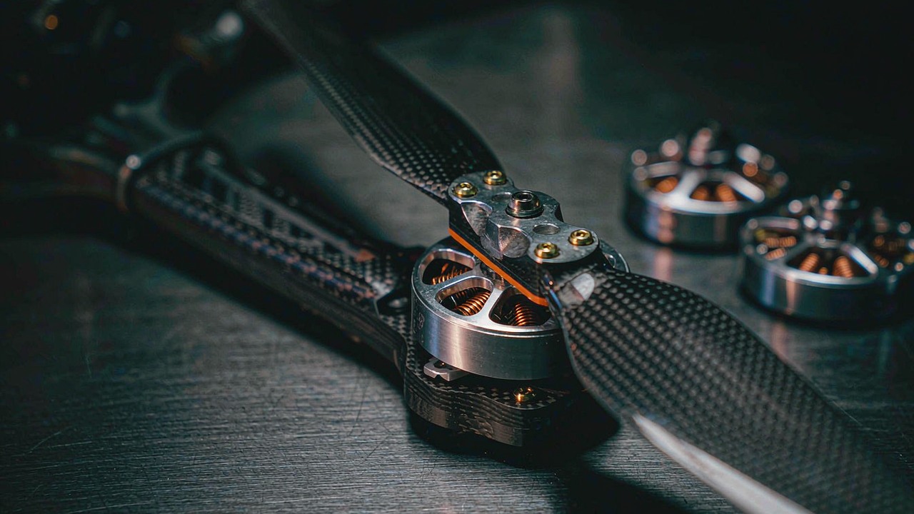
UAV motors are outrunner propulsion units for airframes that have to stay up - multirotors, heavy-lift platforms and VTOL aircraft with a dedicated lift set. The bell carries the propeller directly, so there is no gearbox and the specification is written in thrust, KV, power and mass rather than shaft torque.
What decides the pick
Propeller and cell count first: published thrust always belongs to a specific prop and voltage, and a motor ranked without them cannot be compared. Then KV against the pack - low KV with a large prop for efficiency and heavy lift, high KV with a small prop for response. Then the 180 second power figure, which is the sustained capability rather than a burst number, and the mass, which is paid twice on a multirotor because it is also payload not carried. Stator configuration (12N14P through 36N42P) matters for smoothness and for how the motor behaves at partial throttle.
Where it fits
The category covers industrial UAV and inspection airframes, agricultural sprayers, aerial photography, heavy lift and manned aircraft propulsion. At the light end the MN4006 KV380 delivers 380 W at 68 g; at the top the U15XXL KV29 and U15 II KV80 carry multi-kilogram airframes, with the P80 III Pin covering agricultural payloads.
The manufacturer's release footage for the MN range, useful for judging whether a 68 g to 171 g motor matches the disc area the airframe allows.
ToBMS video pageWatch on YouTubeDrone motors
What it is
Drone motors are the smaller, faster end of aerial propulsion: FPV and racing units measured in tens of grams, fixed-wing and glider motors built for a single efficient operating point, and VTOL lift motors that carry a heavier airframe on a larger disc. Like UAV motors they are thrust devices, but the design points are further apart and the duty cycles are shorter and much more violent.
What decides the pick
In FPV the binding constraints are response and mass: a T-Hobby F30 FPV Drone Motor on a 3-inch build and a 33.5 g unit on a 5-inch build are chosen for how fast they can change thrust, not for efficiency. KV sits high - 1300 to 2150 - because the prop is small and the pack is 4S to 6S. Fixed-wing and long-range work sits at the opposite end: the AT4130 KV230 and the F90 KV1300 are chosen for a sustained cruise point. VTOL lift motors such as the V505 KV260 sit between the two, sized for a hover the airframe has to hold rather than a transient.
Where it fits
FPV racing and freestyle, fixed-wing models, long-endurance platforms and VTOL drones that transition between hover and forward flight. Where an airframe is heavy, slow and staying up for a long time, the UAV Motors category is usually the better starting point.
Gimbal motors
What it is
A gimbal motor is a low-KV, large-diameter direct-drive BLDC motor built for smooth motion at very low speed. There is no gearbox: the motor drives the axis directly, because any backlash or cogging in the drive train shows up as visible jitter in the image. The priorities are therefore different from every other category - cogging torque, torque ripple and low-speed smoothness outrank torque density.
What decides the pick
Payload mass and axis inertia first, since the motor has to hold and accelerate the camera against gravity and vehicle motion. Then the torque needed to hold that payload at the worst-case lever arm, checked against rated rather than peak - a gimbal holds continuously, which is exactly the case rated torque describes. KV is low by design: 9.3 to 255 across the range, with the large GL100 at 3 Nm rated for heavy cinema payloads and the GL30 at 0.08 Nm for a small camera axis. Hollow shafts matter because the wiring has to pass through the axis.
Where it fits
Gimbal systems on UAVs, handheld stabilisers, vehicle-mounted camera rigs and any application where a sensor has to stay pointed while its mount moves. The mid-range GL60 KV25 covers single-axis work at 0.6 Nm rated.
Underwater thrusters
What it is
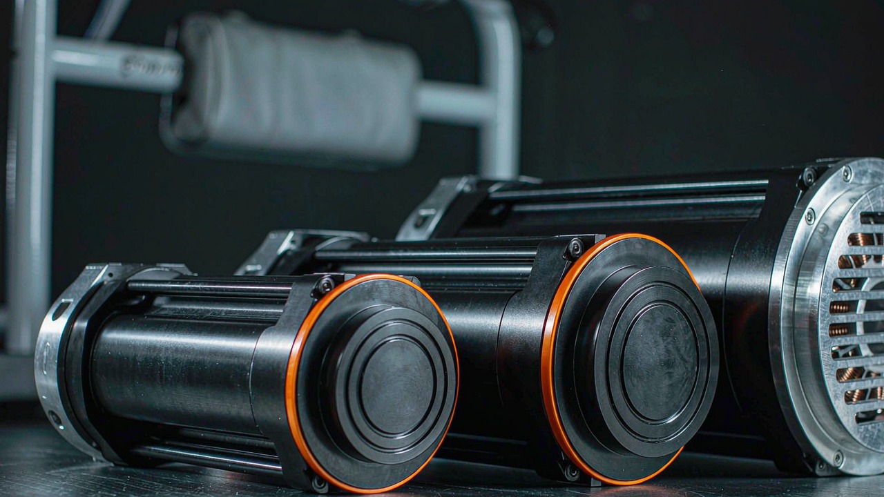
An underwater thruster is a sealed brushless propulsion unit: motor, integrated ESC, ducted propeller and pressure-tolerant or pressure-compensated sealing in one housing. The BLDC motor inside is conventional; everything around it exists to keep water out and to make thrust reversible and proportionable.
What decides the pick
Thrust first, expressed as maximum mooring thrust - the pull the thruster produces at zero speed, which is the honest number for holding station. Then the bus: 36 V or 48 V across the range, with rated power from 360 W to 1315 W. Then the depth rating, which is where the two families diverge: the SW series is rated to 0-30 m while the DW series is listed as 0-350 m, and the units as published should be confirmed with the manufacturer before a deep build is committed. Mass and diameter decide how many units the hull can carry.
Where it fits
ROV thrusters for inspection and intervention, AUV propulsion, and any subsea vehicle that needs vectored thrust. The SW7 at 700 g and 360 W suits small inspection vehicles; the DW25 at 25 kgf and 1315 W is the workhorse end, with the DW10 covering mid-size hulls.
The manufacturer runs the largest DW unit in a tank, which shows the duct, the reversible thrust and the sealing arrangement that separates this category from any other brushless motor.
ToBMS video pageWatch on YouTubeQuasi direct drive actuators
What it is
A quasi direct drive actuator is an integrated module with a deliberately low reduction ratio - 8:1 across this category - sitting between a direct-drive motor and a conventional high-ratio actuator. It keeps enough gearing to reach useful torque while preserving the torque transparency that makes force control possible without a load cell.
What decides the pick
The reason to choose QDD is back-driveability: a low ratio generally improves it, because less friction and inertia is reflected back through the stage. That is what lets a joint absorb an impact, be back-driven by hand during teaching, and estimate contact force from motor current. The cost is that output torque per unit of motor torque is lower, so the motor has to be larger for the same output - which is why the AKE90-8 carries 1400 g to reach 55 Nm rated while a 64:1 robotic actuator reaches comparable torque in a smaller package. Backlash values are recorded on ToBMS, but the measurement condition behind them is not stated; confirm them before relying on the figure.
Where it fits
Legged robots that need compliant contact, arms doing force-controlled assembly, exoskeletons and Rehabilitation Robot where the motor has to yield to the user, and research platforms where torque transparency matters more than peak output. The AKE60-8 at 260 g and 5 Nm rated covers light joints; the AKE80-8 at 12 Nm sits in the middle.
The manufacturer demonstrates the 8:1 modules in joint assemblies, including the back-driving behaviour that defines the category.
ToBMS video pageWatch on YouTubeWhere the categories overlap
Frameless motor, integrated actuator or QDD module
All three end in a rotating joint, and the choice is about who does the integration. A frameless kit gives the lowest mass and the shortest axial length but asks for a housing, bearings and a thermal path. An integrated robotic actuator gives a matched, sealed unit with a matched driver, at the cost of a fixed envelope and a higher mass for the same torque. A QDD module trades some of that torque density for torque transparency and compliant behaviour. Where the joint geometry is still changing, frameless is usually the more forgiving choice; where the geometry is fixed and the schedule is short, an integrated module is.
UAV motor or drone motor
The two aerial categories overlap deliberately: both are outrunner propulsion, and a light industrial quad could plausibly use either. The practical distinction is duty and airframe class. UAV Motors are documented against sustained power, larger discs and multi-kilogram airframes; Drone Motors cover FPV, fixed-wing and VTOL work where the operating point is a burst or a cruise rather than a long hover. If the specification sheet is being read for a 180 second power figure and a mass budget per rotor, start in UAV; if it is being read for throttle response and prop size, start in drone.
Gimbal motors and everyone else
Gimbal motors are the only category where smoothness outranks density, which is why their KV values are low and their diameters are large. Substituting a propulsion motor because the torque figure looks adequate produces an axis that cogs and hunts at low speed. The reverse substitution fails too: a gimbal motor has neither the speed range nor the thermal design for propulsion.
Thrusters: the same motor, a different medium
An underwater thruster contains an ordinary brushless DC motor. What makes it a separate category is everything downstream of the shaft: sealing, pressure tolerance, a ducted propeller, reversible bidirectional drive and corrosion resistance. The specification convention changes accordingly - thrust in kgf rather than torque in Nm - and any comparison with an aerial motor has to go through the propeller and the fluid, not through the motor.
Selection checklist
Run these in order. Each step removes candidates that no amount of specification reading will recover.
Load and duty
- Define the output: shaft torque in Nm, or thrust in kgf at a named propeller and voltage. This alone picks the category group.
- Separate the continuous case from the transient case, and size rated torque against the first and peak torque against the second - remembering that peak is bounded by temperature and driver current, not by a mechanical limit.
- Check the duty cycle against the manufacturer's thermal conditions, not the headline power figure.
- Confirm whether the joint or axis must hold torque at zero speed; if it must, plan for sensors and a driver that reads them.
Mechanics and integration
- Fix the envelope - diameter, stack length or hull space - before comparing torque.
- Decide who supplies the housing, bearings, shaft and thermal path. If the answer is "we do", a frameless kit is in scope; if it is "the supplier", an integrated module is.
- Choose the reduction ratio for the behaviour wanted, not just the torque: high ratio for load holding, low ratio for back-driveability and force transparency.
- Ask for backlash with its unit, and confirm against the datasheet before treating it as a design input.
Electronics and control
- Fix the bus voltage first, then choose KV so the required speed lands inside the voltage rather than outside it.
- Check the driver's continuous and peak current against the torque demanded, and confirm the commutation interface - Hall, encoder or sensorless - matches what the motion profile needs.
- Confirm the control mode available on the driver: torque control is a requirement for compliant joints and force estimation, not a nice-to-have.
- Verify the supplier's published figures on the current datasheet before the design is frozen; records for quantities such as backlash do not always state the measurement condition.
Frequently asked questions
QAre BLDC motors AC or DC?
Both, depending on where the measurement is taken. The supply is DC - a battery or a DC bus - and the controller chops it into a three-phase waveform that drives the stator windings, so the motor itself is effectively a synchronous AC machine with an electronic commutator. The practical implication is that a brushless DC motor cannot be run by connecting it to a DC supply; the driver is mandatory, and its current limit and control mode are part of the motor's real specification.
QWhat does KV mean, and is a higher KV better?
KV is roughly the no-load rpm per volt. It is a winding property, not a quality score: more turns give lower KV with more torque per amp, fewer turns give higher KV with more speed and less torque per amp. The right KV is the one that puts the required speed at the available bus voltage while keeping current - and heat - inside the winding and driver limits. A higher KV on the same voltage means more speed and usually less usable torque at the shaft.
QWhat is the difference between rated torque and peak torque?
Rated torque is what the motor can produce continuously within its thermal limits in the mounting and cooling arrangement the manufacturer specified. Peak torque is a short-duration transient, limited by winding and magnet temperature and by the driver's current limit. Peak is not a mechanical breaking point and should not be treated as one; if the gearbox or shaft strength is what decides the design, that needs to be confirmed with the manufacturer separately. Size the duty cycle against rated and the transient case against peak.
QWhy do some BLDC motors have a gearbox and others do not?
Gearing multiplies torque and reduces speed, so it lets a small, fast motor produce useful output torque - which is how integrated robotic actuators reach tens of Nm. Direct drive has no gear train at all, which removes backlash and reflected inertia and gives the smoothest, most back-drivable output - which is why gimbal motors and frameless joint kits are direct drive, and why quasi direct drive modules deliberately stop at 8:1. The trade is behaviour, not just numbers: a high ratio generally makes the output harder to back-drive, a low ratio generally keeps it transparent.
QCan a brushless DC motor run without sensors?
Yes, if the load is predictable and the motor does not need to produce meaningful torque at zero speed. Sensorless control infers rotor position from back-EMF, which only exists once the motor is turning - fine for propellers, fans and pumps, weakest for a joint holding a pose, a gimbal resisting a gust or a thruster reversing through zero. Applications that must hold torque at standstill, or start under load, need Hall sensors or an encoder.
QHow do I compare motors across categories?
Compare the output convention first. Categories that publish shaft torque - frameless motors, robotic actuators, gimbal motors and QDD modules - can be placed against each other on rated and peak Nm, mass and envelope. Categories that publish thrust - UAV motors, drone motors and underwater thrusters - can only be compared with the propeller, the voltage and the operating point attached. Converting between thrust and torque requires the prop and the fluid; a torque figure and a kgf figure do not belong in the same column.
QWhat limits how small a BLDC motor can be?
Heat and torque density, in that order. Copper loss scales with the square of current, so shrinking the motor while keeping the torque means raising current density and therefore temperature; the small end of every category is bounded by what the winding can shed. Magnet volume sets the torque available in the first place, which is why the smallest frameless kits - around 20 g - sit at fractions of a Nm while a 700 g unit reaches several Nm. Where mass is the binding constraint, check rated torque per kilogram, then confirm the thermal arrangement with the manufacturer.
Official resources
Manufacturer documentation remains the source of truth for torque conventions, thermal ratings, backlash units and current firmware. CubeMars publishes its frameless, actuator and thruster ranges at cubemars.com, and T-Motor publishes its UAV, drone and propulsion ranges at tmotor.com. ToBMS keeps the discovery layer searchable and comparable across both.
Where to go next
Start from the category that matches the mechanical job, then narrow inside it. The full range - every model and specification side by side - is in Product; each of the seven categories has its own page: Frameless Torque Motors, Robotic Actuators, UAV Motors, Drone Motors, Gimbal Motors, Underwater Thrusters and Quasi Direct Drive Actuators. Filter candidates by torque, voltage and mass in Select, then place the finalists against each other in Compare Products.
Each category also has a dedicated guide that goes deeper than this overview: frameless torque motors, robotic actuators, UAV motors, drone motors, gimbal motors, underwater thrusters and quasi direct drive actuators. For applications rather than categories, the humanoid robot, quadruped, ROV and gimbal pages list the motors already matched to those jobs. And the full range of brushless DC motors on ToBMS is one click away from the homepage. Beyond those category guides, the manned end of the UAV and drone ranges has a comparison of its own. Manned Aircraft Propulsion Systems: Three T-Motor U15 Motors Compared sets the U15 II, U15XL and U15XXL side by side.
The short version: pick the category from the mechanical job, fix the envelope, choose KV from the bus voltage and required speed, size rated torque against the duty cycle and peak against the transient, and decide early whether the joint needs to hold torque at zero speed. Everything else in a BLDC motor specification follows from those five.