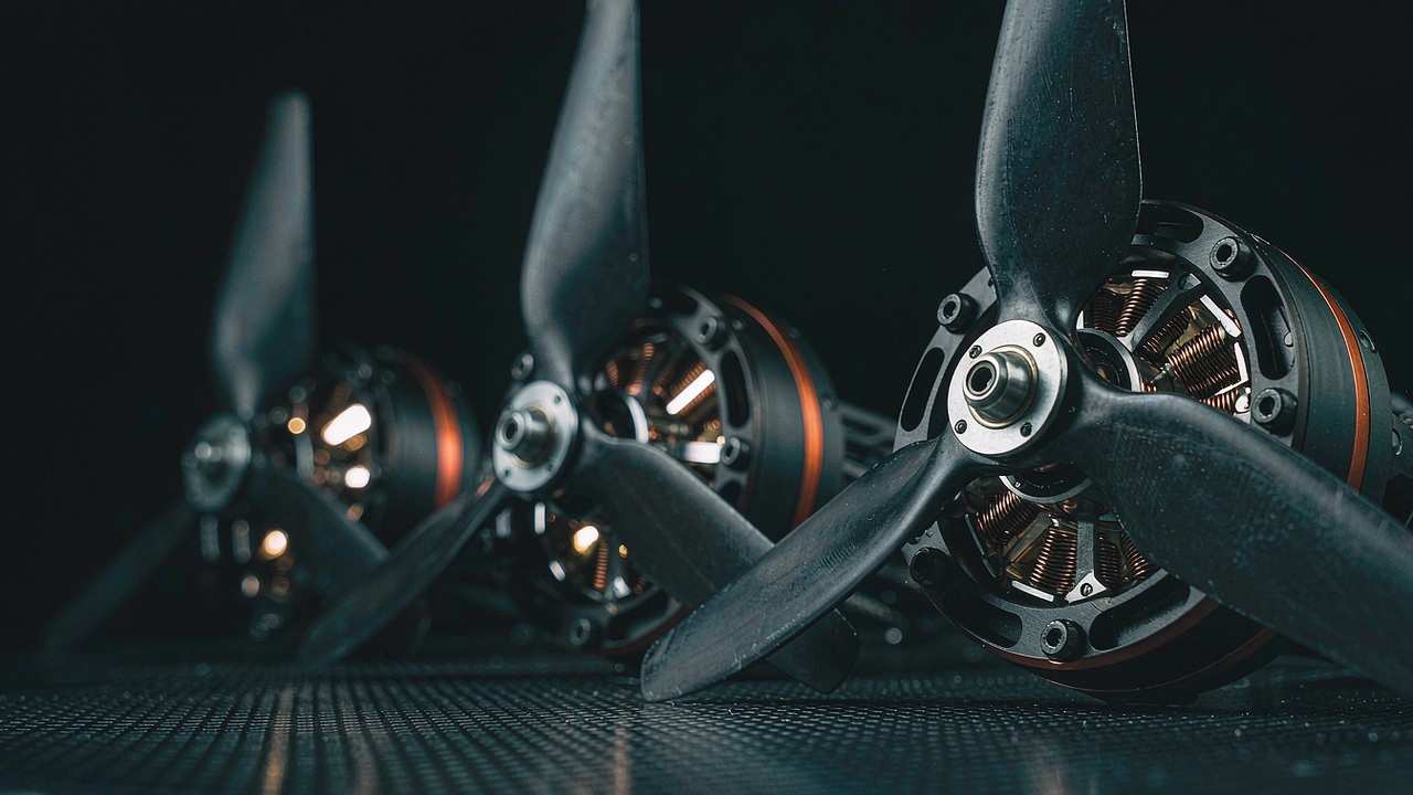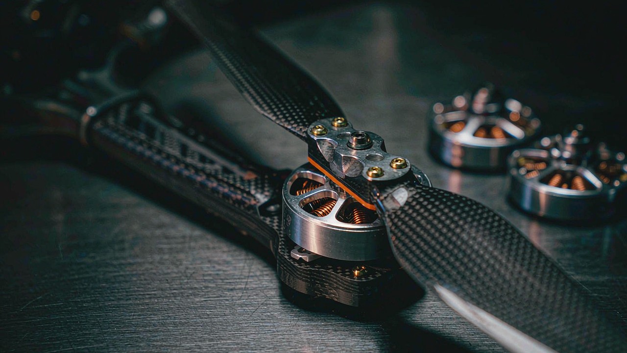
A high thrust drone motor is not the largest unit on a specification sheet; it is the motor that still makes its thrust at the operating point an airframe actually flies. Sizing one starts from the mass the aircraft has to lift, divides that mass between the rotors, and then checks whether the motor can hold its share of the load without running out of thermal margin. Payload class, thrust per rotor and thermal margin are the three quantities that decide the answer, and on a heavy-lift airframe they are also the quantities that set how much motor mass has to be carried to do the job.
This guide works through ten of the records currently listed in the ToBMS UAV Motors category, all of them T-Motor units that the ToBMS records group under Heavy Lift Drone and Agricultural UAV, and sets out which specification settles the choice at each step. Every figure below is taken from the ToBMS product record or from the manufacturer’s published specification; the ratios derived from those figures are labelled as derived, and where a value is not published it is marked as not published rather than inferred from a similar model.
Quick Answer
Payload class comes first, and it is an aircraft figure rather than a motor figure. The eight Navigator records examined here state an aircraft maximum take-off weight directly on the manufacturer’s page, running from 60 kg on the T-Motor MN1115 KV130 UAV Motor to 140 kg on the T-Motor MN1330 KV40 UAV Motor. That number is the all-up weight of the aircraft, not the payload hanging under it; payload is what remains after the airframe, the pack, the avionics and the motors are subtracted, which is why the motor choice follows from a mass budget rather than from a payload figure on its own, and why a heavy payload drone motor is always matched to the airframe rather than to the load alone.
The thrust that a high thrust drone motor has to deliver is then set by dividing the thrust the aircraft needs between the arms. Multirotor practice budgets a multiple of all-up weight so that attitude control keeps authority during manoeuvres and disturbances, and the recorded maximum thrust per motor is therefore a ceiling rather than a working point. Continued control after a rotor failure is a separate fault-tolerance requirement that follows from the airframe configuration, the control allocation and the failure case rather than from the maximum thrust figure alone. A third figure decides whether that ceiling holds in flight, and it is thermal margin: the power and current ratings published for these motors are stated over a short window, and the surface temperature on the manufacturer’s test bench is measured at a particular throttle level and run duration. Ten records cannot be ranked against each other on that basis, because the propeller, the bus voltage and the test conditions change from page to page. What the figures can do is show where the margin sits for one motor, one propeller and one bus, which is the comparison a sizing decision actually needs.
What Counts as a High Thrust Drone Motor
Nothing in the construction of a high thrust drone motor changes at the heavy end of the class. What changes in a high thrust drone motor is which part of the specification becomes the binding constraint. On a small airframe the limit is usually the pack and the wiring, and a high thrust drone motor is chosen to suit a propeller that already fits the frame. On a heavy-lift or agricultural airframe the limit moves to thermal duty and motor mass together, and for these airframes thermal duty and propulsion-system mass can become important coupled constraints as the required payload and mission demands increase, which is what makes the selection problem different at this end of the range.
Thrust per Rotor Against Motor Mass
Two figures sit on opposite sides of every heavy-lift decision and neither can be read alone. Thrust per rotor is what the motor has to produce at the working point; motor mass is what the aircraft pays for that thrust on every flight, and the motors are part of the all-up weight the propulsion system is lifting. The two figures move together across the ten records below: the T-Motor U11 II KV120 UAV Motor is 772 g and records 14159 g of thrust, while the T-Motor MN1330 KV40 is 2750 g and records 75415 g. Between them the mass rises by a factor of about 3.6 and the recorded thrust by a factor of about 5.3, and that difference in slope is what a sizing decision is trading on.
Read the two figures as a pair rather than as a score. A high thrust drone motor that is light for its thrust reduces the mass the propulsion system carries, but it also has less copper and less stator to dissipate the loss it generates, and the two effects are not independent. A high thrust drone motor that is heavy for its thrust carries more material into the thermal problem but adds to the mass the aircraft lifts on every flight and to the inertia the attitude controller has to work against. Which side of that trade is correct depends on the duty the aircraft flies, and the same motor can sit on either side of the line for two different missions.
KV as the First Filter
KV is the speed constant of the winding, expressed in rpm per volt, and on these records it runs from 130 on the MN1115 down to 40 on the MN1330. Its practical role in sizing is to state which cell count and which propeller diameter the motor was wound for. A low KV on a given bus turns the same propeller more slowly, and a low-KV winding can be appropriate for lower-speed, larger-propeller configurations, but the current at a given thrust has to be assessed from the motor–propeller operating data rather than from the KV value, which is what lets a heavy-lift airframe run a large propeller without the current rising beyond what a controller can hold continuously. KV is a match statement rather than a quality figure, and a 24S bus driving a 20 in propeller and a 24S bus driving a 30 in propeller will want different values even for the same thrust target.
The related figure on a high thrust drone motor is stator configuration, and on the Navigator motors it is published as a slot and pole count such as 36N40P or 36N42P. Each of the eight Navigator records here is a high pole-count outrunner with a large diameter stator, from 120.5 mm on the MN11 series to 150 mm on the MN13 series. The KV value reflects the motor’s winding and electromagnetic design; pole count and stator dimensions provide additional context but do not independently determine KV. The two series divide along that line: the MN11 group pairs a 120.5 mm stator with either 12S or 24S, and the MN13 group pairs a 150 mm stator with 14S or 24S. The UAV Motors: Matching KV, Thrust and Mass to Your Airframe works through the same relationship across the wider U, Navigator, P and AT ranges for anyone who wants the general case before the specific one.
How High Thrust Drone Motor Payload Class Is Set
The payload class of an airframe is not a property of the motor, and the figure the manufacturer publishes next to a motor is not a payload rating either. T-Motor states an aircraft maximum take-off weight for each Navigator motor, and that number describes the heaviest aircraft the motor is intended to drive rather than the load such an aircraft can carry. Getting from one figure to the other is a subtraction, and the result depends on how the airframe is built.
Payload Class and Rotor Count
Sizing a high thrust drone motor starts from the all-up weight and subtracts everything that is not payload: the airframe, the pack, the avionics, the payload mount and the motors themselves. What remains is the mass available for the mission equipment, and on a heavy-lift airframe that remainder depends on the airframe, battery, propulsion system, avionics and payload-mount mass within the allowable all-up weight. The declared maximum take-off weights across the eight Navigator records run at 60 kg on the MN1115 KV130, 70 kg on the T-Motor MN1118 KV108 UAV Motor, 80 kg on the T-Motor MN1123 KV53 UAV Motor, 90 kg on the T-Motor MN1315 KV100 UAV Motor, 100 kg on both the T-Motor MN1130 KV45 UAV Motor and the T-Motor MN1320 KV49 UAV Motor, 120 kg on the T-Motor MN1325 KV47 UAV Motor and 140 kg on the MN1330 KV40. The two U-series records, the U11 II KV120 and the T-Motor U13 II KV65 UAV Motor, do not publish an aircraft maximum take-off weight, so no class is assigned to them here.
Rotor count then divides that mass. An airframe of the same all-up weight built on six arms asks more of each motor than the same airframe built on eight, and the difference is not arithmetic alone: the fewer the rotors, the more the aircraft depends on each one, and the larger the share of the control budget that has to be reserved for attitude control and disturbances. A propulsion budget that spends the whole recorded thrust figure on steady flight leaves nothing for that reserve, which is why the fraction of maximum thrust used at hover is a sizing input rather than an outcome.
Thrust Margin at Part Throttle
A high thrust drone motor on a heavy-lift airframe spends most of its flight at part throttle, and the part-throttle region is where the margin lives. The manufacturer’s test data shows how much of the thrust figure is produced at moderate throttle: on the MN1330 KV40 with a 52 x 20 in propeller the bench table records 14117 g at 40 percent throttle against 75415 g at 100 percent, so the upper half of the throttle travel carries the majority of the thrust on offer. Translating that into a working point for a high thrust drone motor means choosing the throttle at which the aircraft hovers with a full load and checking how much travel is left above it.
The second part of the margin is the gap between the thrust a motor records and the thrust it can hold. The Navigator pages publish two per-arm figures side by side, a maximum and a rated value, and the gap between them is wide: the MN1123 KV53 records 47.5 kg maximum against 20-22 kg rated per arm, the MN1325 KV47 records 68.0 kg against 30-32 kg, and the MN1330 KV40 records 75.4 kg against 35-38 kg. That gap is the difference between what the motor can produce on a test bench for a short burst at full throttle and what it is intended to hold as a working load, and a high thrust drone motor is sized on the second figure with the first used as the ceiling it must not be asked to hold.
Efficiency at Part Throttle and Full Throttle
Efficiency is the one quantity in the sizing chain of a high thrust drone motor that the records describe indirectly, and the reason is that thrust per watt is a property of the motor and the propeller together rather than of the motor alone. The manufacturer’s test tables record it as a ratio, in grams of thrust per watt, and the ratio moves with throttle on every motor examined here. On the MN1330 KV40 with a 52 x 20 in propeller the bench table carries 10.61 g/W at 40 percent throttle and 4.64 g/W at 100 percent, and the same shape appears on the U11 II KV120 with a 28 x 9.2 in propeller, at 11.72 g/W against 5.08 g/W. Thrust rises across that range and the thrust per watt does not, which is the arithmetic behind the part-throttle margin discussed above.
Internal Resistance and Winding Loss
Winding copper loss follows an I²R relationship, so resistance sets how much of the input becomes heat at a given operating point, but estimating it from published data requires compatible resistance and current definitions rather than multiplying the phase-to-phase figure by any current value. Across the ten records the published figures span a wide band, from 7.5 mΩ on the MN1315 KV100 to 80±5 mΩ on the U11 II KV120, and the ordering of the band does not follow the thrust ordering: the MN1315 KV100 is one of the higher-thrust records here and also carries the lowest published resistance, while the MN1118 KV108 and the MN1115 KV130 record 13 mΩ and 16 mΩ at 12S and the MN1123 KV53 records 35 mΩ at 24S. Resistance is a winding property of a high thrust drone motor and is quoted for the winding the page describes, so it is read together with the cell count rather than on its own.
Idle Current and No-Load Drag
The no-load side of the account is the idle current, published as 1.5 A at 18 V on the U11 II KV120, 1.7 A at 18 V on the U13 II KV65, and between 2.0 A and 5.7 A at 20 V across the Navigator records. That current covers the loss the motor produces while turning without a load: bearing drag, windage between the rotor and the stator, and the iron loss of a stator being switched at a frequency set by the pole count and the speed. On a large-stator outrunner it is a small fraction of the working current, and its influence on a sizing decision is at the low end of the throttle travel, where the useful thrust is smallest and the share of input spent on no-load loss is largest. On a high thrust drone motor neither the resistance nor the idle current is a figure a choice is made on directly; both are read to follow where the loss goes, which is what the thermal section below then applies to a working point.
Thrust per Rotor and What It Costs in Motor Mass
Once the payload class and the rotor count are fixed, the remaining question is how much thrust each arm has to produce and what the motor that produces it weighs. The two are separate specifications on the page and a single decision in the airframe, because every gram the motor adds is part of the all-up weight the aircraft has to lift, and the thrust that motor makes is part of what lifts it.
Reading the kg Figure
The thrust figure published for a high thrust drone motor is a maximum recorded on a test bench at a stated voltage, propeller and throttle, and reading it correctly means reading those three conditions with it. The ten records below are stated on propellers from a 28 x 9.2 in unit up to a 52 x 20 in unit, on buses from 12S to 22-25S, and the figures run from 14.16 kg on the U11 II KV120 to 75.4 kg on the MN1330 KV40. None of them is a rated thrust in the sense of a value the motor is intended to hold indefinitely, and the Navigator pages separate the two ideas explicitly by publishing a maximum and a rated per-arm figure side by side. Where a sizing decision needs the working value rather than the ceiling, the rated per-arm figure is the one to read, and where the page does not publish one the ceiling is the only published number and has to be treated as such.
Motor Mass per kg of Recorded Maximum Thrust
Dividing the recorded mass of a high thrust drone motor by its recorded maximum thrust gives a derived figure that describes what the thrust costs in mass against that maximum, and on the ten records it lands between 30.0 g and 54.5 g per kg of recorded maximum thrust. It is not a standardised efficiency metric, because the propellers, bus voltages and test conditions differ from record to record. The eight Navigator records sit in a narrow band from 30.0 g on the MN1123 KV53 to 36.5 g on the MN1330 KV40, which is a spread of about one fifth across a thrust range that more than doubles. The two U-series records sit outside that band at the top, and it is the U11 II KV120 that sits highest, at 54.5 g per kg of recorded maximum thrust. The listed specifications do not provide a component-level mass breakdown, so the specific contribution of its structure and winding cannot be isolated from these records alone; the U11 II KV120 is nonetheless the lightest motor here at 772 g and records the smallest thrust at 14.16 kg. For a high thrust drone motor the figure is derived from published values and is not itself a manufacturer specification; it is useful for seeing how the cost of thrust changes across a range, and it is read alongside the thrust figure rather than instead of it.
| Model | Aircraft Maximum Take-Off Weight | Max Thrust | Rated Thrust per Arm | Motor Mass | Motor Mass per kg of Recorded Maximum Thrust | Cell Count | Propeller |
|---|---|---|---|---|---|---|---|
| U11 II KV120 UAV Motor | not published | 14.16 kg | not published | 772 g | 54.5 g | 12S | 28 x 9.2 in |
| U13 II KV65 UAV Motor | not published | 28.7 kg | not published | 975 g | 34.0 g | 22-25S | G32 x 11 in |
| MN1115 KV130 UAV Motor | 60 kg | 33.3 kg | 14-15 kg | 1055 g | 31.6 g | 12S | G36 x 11.5 in |
| MN1118 KV108 UAV Motor | 70 kg | 38.1 kg | 16-18 kg | 1186 g | 31.1 g | 12S | VZ40 x 16.1 in |
| MN1123 KV53 UAV Motor | 80 kg | 47.5 kg | 20-22 kg | 1425 g | 30.0 g | 24S | VZ42 x 16.5 in |
| MN1315 KV100 UAV Motor | 90 kg | 50.2 kg | 20-25 kg | 1780 g | 35.5 g | 14S | VZ40 x 16.1 in |
| MN1130 KV45 UAV Motor | 100 kg | 57.3 kg | 20-25 kg | 1740 g | 30.4 g | 24S | NS47 x 18 in |
| MN1320 KV49 UAV Motor | 100 kg | 59.0 kg | 25-28 kg | 2070 g | 35.1 g | 24S | NS45 x 17.5 in |
| MN1325 KV47 UAV Motor | 120 kg | 68.1 kg | 30-32 kg | 2425 g | 35.6 g | 24S | NS47 x 18 in |
| MN1330 KV40 UAV Motor | 140 kg | 75.4 kg | 35-38 kg | 2750 g | 36.5 g | 24S | NS52 x 20 in |
Aircraft maximum take-off weight, thrust, motor mass, cell count and propeller as published by the manufacturer and carried in the ToBMS product record; motor mass is quoted including cables. Motor mass per kg of recorded maximum thrust is derived here from the recorded mass and the recorded maximum thrust and is not a manufacturer figure; because the test conditions and propellers differ, it should not be read as a standardised efficiency metric or as a direct measure of in-flight payload capability. The Navigator pages state the per-arm values as Max Thrust/Arm and Rated Thrust/Arm; the two U-series pages state a single maximum thrust figure and no rated per-arm value, and the cells reading not published are left open rather than filled from a comparable model. Every manufacturer test table is read against the propeller block, throttle step and bus voltage printed on the page it came from, because the column order and the efficiency unit are not the same on the U-series pages as on the Navigator pages. No thermal or efficiency figure is compared across the models in this table: the propeller, the bus voltage, the throttle level and the run duration differ from page to page, and the manufacturer states that bench figures are intended as a reference for that motor rather than as a basis for comparing motor types.
Propeller Diameter Behind Each Thrust Figure
The propeller matched to a high thrust drone motor is not an accessory to the thrust figure; it is part of the definition of it. The thrust recorded for a motor is produced by the propeller it was tested with, and changing that propeller moves the motor–propeller operating point and can change both thrust and current draw, so the records here are read with the test conditions attached. How far the propeller sets the result is visible here: the two records here with the closest KV values, the MN1130 KV45 at 45 and the MN1325 KV47 at 47, are tested on the same NS47 x 18 in propeller yet record 57.3 kg against 68.1 kg, so the difference sits in the stator and the winding rather than in the propeller. Propeller choice is bounded by the airframe before it is bounded by the motor, since the disc diameter has to clear the arms and the frame, and by tip speed, since a large propeller on too high a KV will exceed the speed at which the blade tips stop being efficient. On an agricultural airframe the same constraint appears as a spray pattern question, which the BLDC Motors for Agricultural UAV: KV, Stator Size and Part-Throttle Torque takes up from the duty-cycle side.
Thermal Margin in a High Thrust Drone Motor
Thermal margin in a high thrust drone motor is the difference between the heat it produces at a working point and the heat it can dissipate without the winding or the magnets reaching a temperature at which the published figures stop applying. It is the quantity a thrust figure cannot describe, because the same motor asked to hold the same thrust on a larger propeller, a lower cell count or a longer climb will reach a different temperature to get there. The records examined here describe that limit in three separate ways, and reading them together is what turns a thrust figure into a working point.
The 180 s Power and Current Rating
The first description is the power and current rating, and on every record here it is stated over a 180 s window rather than as a continuous value. The Navigator records publish it as a maximum power over 180 s alongside a peak current: 2816 W and 180 A on the MN1115 KV130, 2230 W and 192 A on the MN1118 KV108, 2400 W and 108 A on the MN1123 KV53, 3218 W and 132 A on the MN1130 KV45, 3300 W and 248 A on the MN1315 KV100, 2900 W and 150 A on the MN1320 KV49, 3400 W and 170 A on the MN1325 KV47 and 3400 W and 177 A on the MN1330 KV40. The two U-series records state the same two quantities the other way round in the ToBMS record, with the 180 s power held on the maximum power line and the 180 s current on the peak current line: 2783 W and 57.3 A on the U11 II KV120, and 6720 W and 68 A on the U13 II KV65. The window is the operative part of the specification. A 180 s rating describes a burst, and a heavy-lift airframe that flies a ten-minute mission spends most of it well below that figure and has to be sized so that the sustained current sits inside the continuous capability of the winding, not against the burst number.
Copper Loss, Cooling Path and Mounting
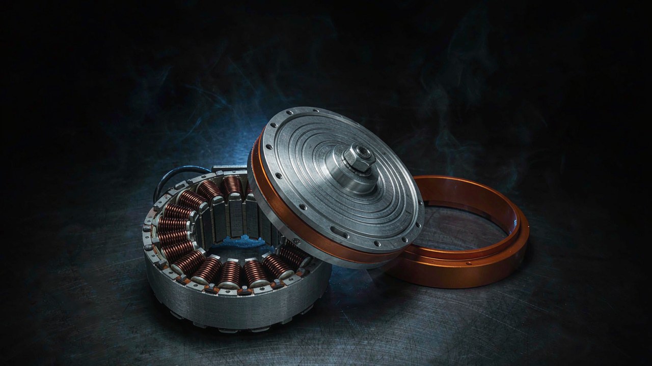
The second description is the loss itself. Copper loss is an important contributor to the heat a high thrust drone motor produces in flight and increases with the square of the current under a consistent resistance definition, while iron and mechanical losses also contribute with their relative importance depending on the operating point; the copper term is set by the phase-to-phase resistance published for the motor: 7.5 mΩ on the MN1315 KV100, 13 mΩ on the MN1118 KV108, 16 mΩ on the MN1115 KV130, 17.5 mΩ on the MN1325 KV47, 19.5 mΩ on the MN1330 KV40, 20.5 mΩ on the MN1320 KV49, 35 mΩ on the MN1123 KV53, 38 mΩ on the MN1130 KV45, 73 mΩ on the U13 II KV65 and 80±5 mΩ on the U11 II KV120. Iron loss and the no-load drag covered earlier add a smaller amount. The heat that copper loss produces then has to leave the motor, and the path it takes is part of the specification rather than an afterthought: the Navigator pages describe a one-piece die-cast cooling fin structure around the stator, state that it doubles the heat dissipation area compared with a split cooling structure, and state that it reduces winding temperature by 5 ℃ to 8 ℃. The materials behind that path are published as well, at a 150 ℃ coating on the stator, a 220 ℃ copper wire and magnets rated to 180 ℃, with an IP45 enclosure and a stated operating range of -30 ℃ to 55 ℃. Mounting matters for the same reason, because the arm is the heat sink the motor conducts into, and a motor bolted to a plate with poor contact runs hotter than the same motor on a machined mount of the same mass.
Where the Thermal Margin Runs Out
The third description of a high thrust drone motor is the measured surface temperature, and it is the figure that makes the first two concrete. On the Navigator records the manufacturer states the motor surface temperature after running at 80 percent throttle for 10 minutes at an ambient of 25 ℃, and across the winding blocks those pages publish the values run from 82 ℃ to 122 ℃. Each one belongs to the propeller, bus voltage and cell count printed on the same page, so the band describes the range the measurements occupy rather than an ordering, and the manufacturer notes that bench figures are intended as a reference for that motor rather than as a basis for comparing motor types. The two U-series records state their surface temperature differently again, measured at 100 percent throttle with the run duration stated at one, two, five or ten minutes depending on the propeller block and an ambient of 19 ℃ on the U11 II page, where that page states one, which is why no temperature is compared across models in this guide.
What the surface temperature of a high thrust drone motor does support is a margin check. The recorded surface temperature provides a useful reference for evaluating thermal behaviour under the stated test conditions, but it does not directly establish winding or magnet temperature. Assessing thermal margin under actual flight conditions requires consideration of internal temperature rise, ambient conditions, cooling, mounting and duty cycle, read against the temperature limits the manufacturer states for the motor. A large-stator outrunner in this class has enough thermal mass that a short overload moves the temperature slowly, which is why a burst rating is useful, and it also has enough thermal inertia that a sustained overload takes a long time to show and a long time to clear. The margin in a high thrust drone motor is therefore spent by the duty profile as a whole rather than by any single moment, and on an agricultural airframe that flies repeated loaded cycles the cumulative effect is what the hull temperature reflects. The duty-cycle side of that question is worked through in BLDC Motors for Industrial UAV: Duty Cycle, Redundancy and Payload, and the efficiency side of it, where thrust per watt falls as throttle rises, is the same mechanism seen from the input end.
T-Motor U11 II and U13 II in the Heavy-Lift Class
The two U-series records are the lightest motors in this group and they sit at the lower end of the thrust range, which makes them the natural starting point for an airframe whose all-up weight is modest by the standards of this class. Neither page publishes an aircraft maximum take-off weight, so the class is set here from the thrust and cell count each one records rather than from a declared figure.
U11 II KV120
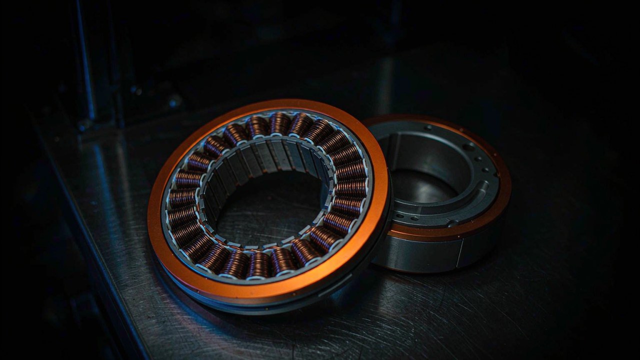
The T-Motor U11 II KV120 UAV Motor is a 772 g outrunner in a 79.5 x 51.6 mm body with a 15 mm shaft and a 12N14P stator, and it is a 12S unit with a recorded maximum thrust of 14.16 kg on a 28 x 9.2 in propeller at 48 V. Its winding records 80±5 mΩ of phase-to-phase resistance with an idle current of 1.5 A at 18 V, and its published 180 s figures are 2783 W and 57.3 A. The manufacturer’s test table for this motor carries three propeller blocks, on 26 x 8.5 in, 27 x 8.8 in and 28 x 9.2 in units, recording 12114 g, 12617 g and 14159 g at full throttle, which is a useful reminder that the headline figure belongs to the largest propeller tested rather than to the motor alone. At 12S and just under 800 g, this record suits an airframe where the payload is small in absolute terms but the rotor count is low enough that the motor still has to produce a serious thrust figure per arm.
U13 II KV65
The T-Motor U13 II KV65 UAV Motor is the step above it: 975 g in a 100 x 60 mm body with a 15 mm shaft and a 36N42P stator, wound for a 22-25S bus against a recorded maximum thrust of 28.7 kg on a G32 x 11 in propeller. It records 73 mΩ of resistance with an idle current of 1.7 A at 18 V, and its 180 s figures are 6720 W and 68 A. The higher cell count is what separates it from the U11 II rather than the thrust figure alone, because a 22-25S bus turns a larger propeller at a lower current for a given thrust, and the manufacturer describes the motor as intended for heavy loads and industrial use over an extended service life. The test table again carries more than one propeller block, with a G30 x 10.5 in unit recording 24744 g and the G32 x 11 in unit recording 28711 g at full throttle. Between the two U-series records the pair covers a range from a light industrial airframe up to the entry point of the Navigator group, and the Heavy-Lift Drone Motors: Three T-Motor Options from 2.85 kg to 101 kg Thrust places both of them in a wider payload-led comparison that also covers the U5 and the U15 series.
T-Motor MN Series Motors for Heavy Lift and Agriculture
The eight T-Motor MN motor records examined here form two families that differ in stator diameter rather than in construction. The MN11 group carries a 120.5 mm stator and the MN13 group a 150 mm stator, and within each family the models scale by stack length while the winding changes with the cell count. All eight are large-stator outrunners with an external electronic speed controller, and each page states an aircraft maximum take-off weight alongside the thrust and thermal figures, which makes this group the part of the range where a high thrust drone motor can be matched to an airframe class directly from published values.
MN1115, MN1118, MN1123 and MN1130
The MN11 records share a 120.5 mm stator diameter and grow in length from 47.9 mm to 65.9 mm across the four models, and the thrust rises with it from 33.3 kg on the MN1115 KV130 to 57.3 kg on the MN1130 KV45. The T-Motor MN1115 KV130 UAV Motor is the entry point at 1055 g, a 36N40P stator and a 12S bus, recording 33.3 kg on a G36 x 11.5 in propeller with a declared aircraft maximum take-off weight of 60 kg; its 180 s figures are 2816 W and 180 A and its winding records 16 mΩ with an idle current of 2.7 A at 20 V. The T-Motor MN1118 KV108 UAV Motor is 1186 g on the same 12S bus with a 36N40P stator and records 38.1 kg on a VZ40 x 16.1 in propeller at a declared 70 kg, with 2230 W and 192 A over 180 s from a 13 mΩ winding and an idle current of 3.3 A at 20 V. Both pages carry a second winding block as well, at 110 KV on the MN1115 and 90 KV on the MN1118, which is why the KV value has to be read with the model rather than from the series name.
The T-Motor MN1123 KV53 UAV Motor moves to a 24S bus at 1425 g in a 58.9 mm body, recording 47.5 kg on a VZ42 x 16.5 in propeller at a declared 80 kg, with 2400 W and 108 A over 180 s and a 35 mΩ winding. The T-Motor MN1130 KV45 UAV Motor closes the family at 1740 g in a 65.9 mm body, 57.3 kg on an NS47 x 18 in propeller at a declared 100 kg, 3218 W and 132 A over 180 s from 38 mΩ, which places the record in the heavy payload drone motor band at a declared 100 kg. The step from 12S to 24S inside one stator family is the clearest illustration of what cell count does here: the MN1123 and the MN1130 produce their thrust at 108 A and 132 A where the MN1118 needs 192 A, and under comparable operating conditions a higher bus voltage reduces the supply current needed for a given electrical power, though the current figures across these models also reflect their different propellers, windings and thrust outputs rather than bus voltage alone; the higher resistance of the 24S windings is the other side of that trade.
MN1315, MN1320, MN1325 and MN1330
The MN13 records carry a 150 mm stator and scale in length from 51 mm to 65 mm, and it is in this family that the declared aircraft maximum take-off weights reach their highest values. The T-Motor MN1315 KV100 UAV Motor is the outlier of the group in two ways: at 14S it is the lowest cell count in the family, and at 100 KV it is the highest winding, which together produce 50.2 kg on a VZ40 x 16.1 in propeller at a declared 90 kg with a peak current of 248 A over 180 s. Its 7.5 mΩ winding is the lowest resistance published across all ten records here, which is the design response to carrying that current. The T-Motor MN1320 KV49 UAV Motor returns to 24S at 2070 g and records 59.0 kg on an NS45 x 17.5 in propeller at a declared 100 kg, with 2900 W and 150 A over 180 s and a 20.5 mΩ winding.
Above it the T-Motor MN1325 KV47 UAV Motor records 68.1 kg on an NS47 x 18 in propeller at a declared 120 kg from 2425 g, with 3400 W and 170 A over 180 s, and the T-Motor MN1330 KV40 UAV Motor closes the range at 2750 g with 75.4 kg on an NS52 x 20 in propeller at a declared 140 kg, 3400 W and 177 A over 180 s from a 19.5 mΩ winding. Both of the two largest records state a rated per-arm figure alongside the maximum, at 30-32 kg and 35-38 kg respectively, which is the value a working point is sized against. The manufacturer’s own T-Motor Navigator MN Series Heavy-Lift UAV Motors: Official Release Video covers the series upgrade that produced these records, and the agriculture-facing end of the same family is worked through in the BLDC Motors for Agricultural UAV: KV, Stator Size and Part-Throttle Torque.
A High Thrust Drone Motor Selection Checklist
The sequence below is the order in which the figures for a high thrust drone motor have to be read, because each step constrains the one after it and none of them can be settled from a motor page alone.
- Total the all-up weight including the motors and the pack, then subtract everything that is not mission equipment. The remainder is the payload the airframe can actually carry, and it depends on the airframe, battery, propulsion system, avionics and payload-mount mass within the aircraft’s allowable all-up weight.
- Divide the thrust the aircraft needs between the rotors, and apply a control margin before the motor is chosen rather than after. The recorded maximum thrust per arm is a ceiling, and a budget that spends all of it on steady flight leaves no reserve for attitude control, disturbances or the intended manoeuvre envelope.
- Fix the cell count from the pack decision, then choose KV so that the propeller diameter the airframe allows reaches its working point at a sensible throttle. KV is a match between bus voltage and propeller, not a performance ranking.
- Read the thrust figure against the propeller, the voltage and the throttle step printed beside it, and prefer a rated per-arm value to a maximum where the page publishes both.
- Estimate the copper loss from the winding resistance and the expected working current only after confirming that the two published values share the same measurement convention, then read the surface temperature the manufacturer records under its own stated conditions alongside the temperature limits stated for the winding and the magnets.
- Check the current a sustained climb draws against the 180 s figure, not against the burst number, and confirm the hover current leaves the window free for control transients.
- Confirm the mechanical interface: shaft diameter, mounting pattern, envelope, cable length and lead gauge have to suit the arm before any of the electrical figures matter.
- Record which values came from the manufacturer’s datasheet, which came from the ToBMS product record and which were derived for the comparison, so that a later revision can be checked against its source.
Three further guides extend sideways from this one. The UAV Motors: Matching KV, Thrust and Mass to Your Airframe covers the whole category from the airframe side and reaches the Navigator, P and AT ranges as well. The Long Endurance UAV application takes the same motors into the efficiency, mass and bus voltage argument, worked through in BLDC Motors for Long Endurance UAV: Efficiency, Mass and Bus Voltage. For the smaller end of the family, where response and battery life dominate instead of thrust per arm, the Drone Motors category and the Industrial UAV application cover the airframes this class of motor is too heavy for.
FAQ
QHow much thrust per rotor does a heavy-lift drone need?
The thrust per rotor a high thrust drone motor has to produce follows from the all-up weight and the rotor count rather than from the payload alone. Total the airframe, the pack, the avionics, the mission equipment and the motors, divide by the number of arms, then multiply by a control margin so that the aircraft keeps control authority through manoeuvres, disturbances and the wind gust case. On the records here that lands an aircraft of around 60 kg all-up on a rated per-arm figure of 14-15 kg, and one of 140 kg on 35-38 kg. None of these motors publishes a hover-rated thrust value, so the hover point is confirmed from the manufacturer’s test data at the intended voltage, propeller and throttle.
QWhat KV does a high thrust drone motor use?
Between 40 and 130 across the ten records examined here, and the value inside that band is set by the cell count and the propeller rather than by the thrust target. A 12S unit turning a 36 in propeller sits at 108 or 130 KV, and a 24S unit turning a 47 in or 52 in propeller sits at 45, 47 or 40 KV. The MN1315 KV100 shows how the two inputs interact: at 14S it carries a higher KV than its 24S siblings precisely because the lower bus needs the higher speed constant to reach the same operating point.
QIs a low KV motor always better for a heavy payload?
No, and the records here show the reason. KV is a match statement between the bus voltage and the propeller, so it is only low or high relative to a particular pair of them. The MN1115 KV130 is the highest KV in this group at 130 and still declares a 60 kg aircraft maximum take-off weight, because its 12S bus and its 36 in propeller are what that winding was matched to. A low KV on the wrong bus or behind too small a propeller produces less thrust at the same current, not more, and a low KV on too large a propeller reaches the throttle ceiling before it reaches the thrust the airframe needs.
QWhich T-Motor MN motors suit an agricultural drone?
The high thrust drone motor choice for a spray aircraft tracks the loaded duty cycle rather than the tank size, because a spray aircraft flies repeated cycles at high mass and needs the part-throttle region to stay efficient. The MN11 family is the natural band for a smaller spray airframe, with the MN1115 KV130 at a declared 60 kg and the MN1118 KV108 at 70 kg on a 12S bus, and the MN13 family covers the larger airframes from the MN1315 KV100 at 90 kg to the MN1330 KV40 at 140 kg. The BLDC Motors for Agricultural UAV: KV, Stator Size and Part-Throttle Torque works through that duty cycle in detail.
QWhat bus voltage does a high thrust drone motor need?
The record states the cell count each winding is specified against, and on these ten it runs from 12S to 22-25S. The choice matters because the current needed for a given power falls as the bus rises, which is why the MN1118 KV108 draws 192 A for its thrust on 12S where the MN1130 KV45 draws 132 A on 24S for more of it. A higher bus reduces the current the controller and the harness have to carry, at the cost of more cells in series and a heavier pack, and the winding resistance published for each motor belongs to the bus it is specified against rather than to the motor in the abstract.
QDoes a 180 s power rating mean the motor can run at that power continuously?
No. The 180 s figure published for a high thrust drone motor is a burst rating over a stated window, and the sustained capability is lower and is set by the temperature the winding and the magnets can hold rather than by the peak the bench test reached. Where the manufacturer publishes a rated per-arm thrust alongside the maximum, as on the MN1123 KV53 at 20-22 kg, the MN1325 KV47 at 30-32 kg and the MN1330 KV40 at 35-38 kg, that rated value is the one to size a sustained duty against. The recorded surface temperatures show what a burst costs: the Navigator pages state them after 10 minutes at 80 percent throttle, which is a duty a heavy-lift airframe can reach in normal use.