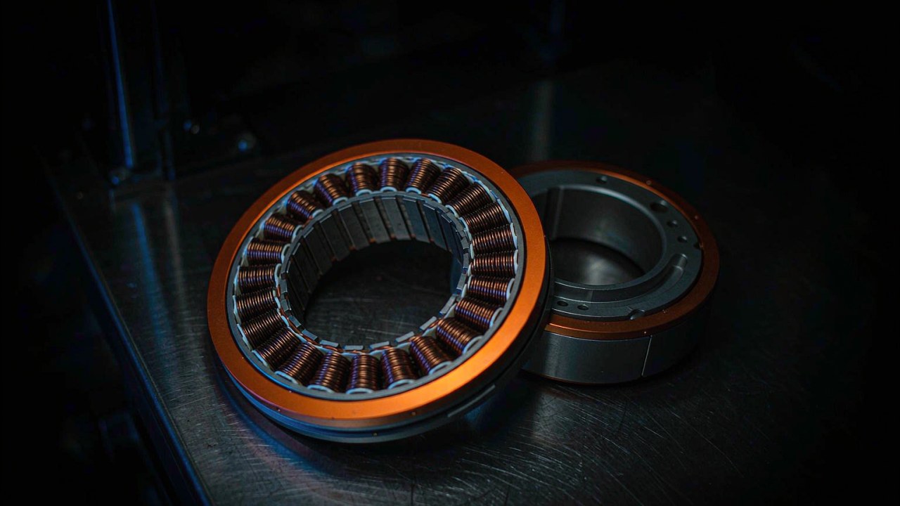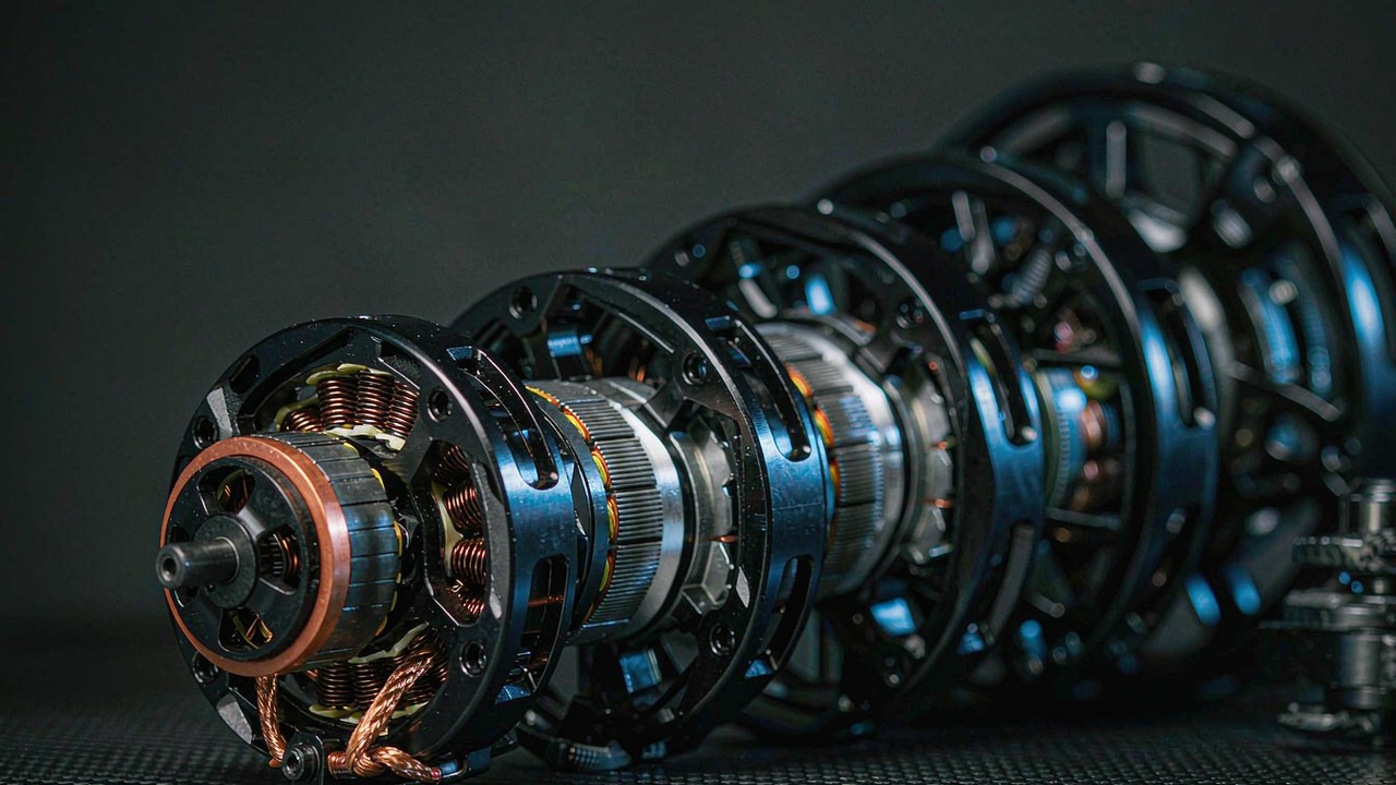
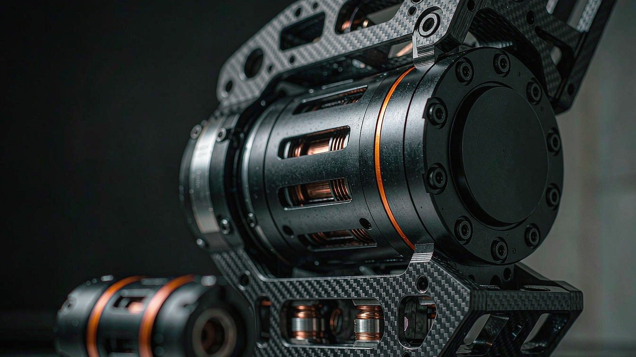
A humanoid robot is a torque problem distributed across every powered joint in the body, and the three numbers that describe each of those joints - how much torque it must hold, how fast it must move, and how much mass the limb can carry - are not independent of each other. Move one and the other two follow. Selecting a BLDC motor for a humanoid robot therefore means finding the point where the three curves intersect for each joint in turn, and then checking that the published record actually supports the point that has been chosen. Get the order wrong and the machine either cannot stand up or cannot lift its own feet.
Quick Answer
The three quantities are linked by two variables: the reduction ratio between motor and joint, and the bus voltage the motor runs on. A low ratio such as 6:1 keeps the joint fast and backdrivable but needs a large motor to make useful torque; a high ratio such as 64:1 makes large torque from a small motor but spends speed and much of the joint's ability to be pushed around by an external load. The ratio is chosen from the joint's duty, the mass follows from the ratio and the torque, and the published peak torque is a short-window claim that should not be used as the working number.
On ToBMS the Humanoid Robot application gathers the CubeMars integrated actuators that serve humanoid joints, from a 262 g unit with a 10:1 stage to a 1396 g hollow-shaft unit with 222 Nm of published peak torque. This guide sets out how torque, speed and size are matched joint by joint, and reads eight of those units as one specification set.
Why a Humanoid Joint Is a Trade Between Torque, Speed and Size
A humanoid platform differs from other machines in that its structure and its payload are the same object. An industrial arm is anchored, its links only have to carry their own inertia and the tool, and the base can be made as heavy as the customer will tolerate. A humanoid robot has to carry its actuators, its battery and its electronics on the same limbs that do the work, and those limbs also have to be moved accurately enough to balance. Every gram added at the knee is a gram the hip has to swing, and every gram added at the hip is a gram the ankle has to correct for.
The duty arrives before any model number
The first number in a joint specification is not a torque. It is a description of what the joint does over one cycle: how long it holds a static load, how long it moves against gravity, how often it accelerates, and how much of that time it spends at low speed under load. A standing hip holds a share of body mass for minutes at a time with almost no motion. A walking knee absorbs an impact in a few tens of milliseconds and then swings freely. An elbow in a manipulation task may spend most of a shift holding a tool at a near-constant angle. These are three different thermal and electromagnetic problems, and they are solved by different points on the torque-speed plane.
Support phase and swing phase ask for opposite ends of the curve
A leg joint alternates between two duties. In support phase the joint is close to stationary under a load that may exceed body weight, which is a torque requirement with almost no speed component. In swing phase the same joint has to move through a large angle quickly with almost no load, which is a speed requirement with almost no torque component. A single motor has to satisfy both, and the reduction ratio is what decides how the compromise is split. High ratio serves the support phase and penalises the swing phase; low ratio does the reverse. This alternation, rather than any single figure, is what makes the leg joints of a bipedal machine harder to specify than a comparable axis in a fixed industrial arm, and it is the first thing to look at when the humanoid robot joints of a new platform are being divided between actuator classes.
Reflected inertia is what the control loop actually fights
Between the motor and the joint output sits the gearbox, and the gearbox divides the rotor's inertia by the square of the ratio on the way out. A high ratio therefore presents the controller with a very small apparent inertia at the joint, which makes position control easy and force control difficult, because the joint can no longer tell what it is pushing against. A low ratio reflects more of the rotor inertia to the output, which makes the joint feel the world and back-drive predictably, and which is why quasi-direct-drive joints with 8:1 or 9:1 stages are used where a robot has to make contact with unknown objects or with a human. The same ratio that sets torque and speed also sets this behaviour, so it is not a mechanical detail that can be fixed later in software.
Balance recovery is a transient the rating window has to cover
Bipedal balance is maintained by corrective torques applied within a fraction of a second of a disturbance, and the magnitude of those corrections can be several times the torque needed to stand still. This is the transient that a joint's published peak torque has to cover, and it is the reason why, in the current ToBMS actuator set, peak-to-rated ratios extend to roughly three times in some models. A joint specified only against its static load will hold a standing pose and then fail to recover from a push, which in a humanoid platform is a fall rather than a missed cycle.
How the Reduction Ratio Converts Speed into Torque
The reduction ratio is the single most useful number in a humanoid joint specification, because it maps every quantity on the motor side onto the joint side in a fixed way. Once the ratio is known, the joint's speed is the motor's speed divided by it, its torque is the motor's torque multiplied by it, and the published figures for the two can be checked against each other.
Joint speed is motor speed divided by the ratio
Every speed quoted for an integrated actuator is an output speed, which is the number the joint sees. The 485 g AK80-6 KV100 with its 6:1 stage publishes 800 rpm at no load, while the 850 g AK80-64 with its 64:1 stage publishes 37 rpm on a 24 V bus - a factor of about twenty-two in output speed produced by a difference in ratio, not by a difference in motor quality. For a joint, revolutions per minute are an awkward unit, so it is worth converting: 1 rpm is 6 degrees per second, which makes the 800 rpm unit a 4800 degrees per second joint at no load and the 64:1 unit a 222 degrees per second joint at the same point. A hip that has to swing through 60 degrees in 300 ms is asking for 200 degrees per second of sustained output, and that single requirement rules out a large part of the high-ratio end of any actuator range.
Torque multiplies by the same ratio, less what the gearing takes
The multiplication is real but not free. A 6:1 stage turns 6 Nm at the motor into roughly 36 Nm at the joint minus friction and the losses in the gear mesh, and a 64:1 stage turns 0.75 Nm into roughly 48 Nm by the same arithmetic. That is why the heaviest units in a range are not automatically the strongest ones: the 750 g AK60-39 V3.0 publishes 72 Nm of peak torque through a 39:1 stage, while the 850 g AK80-64 publishes 120 Nm through a 64:1 stage, so a 100 g mass difference buys a 67 per cent torque advantage because the ratio is doing the work. The ratio also sets the efficiency penalty, because each additional reduction stage costs a small percentage of the power passing through it and adds its own contribution to backlash.
KV times the bus voltage sets the speed on the motor side
KV is the motor-side constant: it is the speed the rotor turns per volt of applied bus voltage, before the reducer. Multiplying KV by the bus voltage and dividing by the ratio gives an estimate of the output no-load speed, and that estimate can be checked against the published figure as an arithmetic cross-check on the record. For the AK45-10 V3.0 KV75 on 24 V through 10:1, 75 multiplied by 24 and divided by 10 gives 180 rpm against a published 180 rpm. For the AK60-6 V1.1 KV140 on 24 V through 6:1, the estimate is 560 rpm against a published 560 rpm; for the AK80-6 KV100 on 48 V through 6:1 it is 800 rpm against 800 rpm; and for the AK70-9 V3.0 KV60 and the AK10-9 V3.0 KV60, both on 48 V through 9:1, it is 320 rpm against 320 rpm in both cases. The correspondence is not universal - the AKH70-48 V1.0 KV41 on 48 V through 48:1 estimates at 41 rpm against a published 35 rpm - which is exactly why the published output speed, and not a value derived from KV, is the number to design against.
A high ratio buys torque and spends backdrivability
Two effects work against a joint as its ratio rises. The first is that the reflected inertia at the output falls with the square of the ratio, so the joint becomes easier to command and harder to feel. The second is friction: a multistage reducer resists torque applied from the output side, and at high ratios that resistance can be large enough that the joint no longer moves when a person or a surface pushes it. In this set the lower-ratio units publish ratios of 6:1, 9:1 and 10:1, while the load-carrying units run at 39:1, 48:1 and 64:1, and the split between those two groups follows the question of whether the joint is expected to make compliant contact or to hold a large load quietly. Backlash is the companion specification and moves the other way: the units in this set publish figures between 0.18 and 0.55°, and a lower ratio with a tight backlash figure is the combination that gives a joint its characteristic of feeling rigid under hand pressure while still being pushed.
Matching Torque: Rated, Peak and the Window Behind Each
Torque is the axis on which most humanoid joint decisions are first made and on which most of them are first made wrong. Three distinct numbers appear in a manufacturer's record, and they answer three different questions.
Peak torque is a window, not a capability
Peak torque describes what the actuator can produce for a short interval - typically the time it takes to accelerate a limb or to arrest a disturbance - without exceeding the drive's current limit or demagnetising anything. It is the correct figure for a balance recovery event or for the first instant of a lift, and it is the wrong figure for anything that has to be repeated. In this set the peak-to-rated ratio runs from 2.0 on the AK80-6 to 3.4 on the AK70-9 V3.0, so two actuators with the same rated torque can differ by more than half in the transient they will deliver. Reading the peak column alone collapses that difference and produces a shortlist that will overheat in continuous service.
Rated torque is bounded by the winding's thermal path
Rated torque is a thermal statement. It is the torque the actuator can hold indefinitely with the winding staying within its insulation class, and it therefore depends on how the heat leaves the stator - through the housing, into the mounting structure, and away from the joint's own enclosure. That is why the rated figure is lower in a small sealed housing than in a large one for the same motor, and why the rated torque of a joint on the end of an arm is a different proposition from the same joint bolted to a hip bracket with a large thermal mass behind it. Rated figures in this set run from 2.5 Nm at the 262 g end to 74 Nm at the 1396 g end, and the rated number is the one that should be compared against the joint's average load rather than against its worst case. An arithmetic check that often closes the loop here is rated torque multiplied by rated speed in radians per second against the published rated power: the AK60-6 V1.1 gives 3 Nm at 420 rpm for 132 W against a published 130 W, the AK70-9 V3.0 gives 231 W against 231 W, the AK60-39 V3.0 gives 176 W against 176 W, and the AK10-9 V3.0 gives 443 W against 442 W. Where the two do not close, the difference is usually traceable to the bus voltage at which the speed was quoted.
Holding torque at standstill is a current question
A joint that stands still under load is not doing zero work from the winding's point of view. The drive has to push current into the phases to hold the position, and the resulting copper loss is the same as if the joint were moving slowly. A standing humanoid therefore has a standing power draw that scales with the holding torque of every loaded joint in the posture, and the current at the rated operating point is the figure that matters: in this set the rated current runs from 1.9 A at the AK45-10 V3.0 on 24 V to 10.7 A at the AK10-9 V3.0 on 48 V. On a battery-powered platform that draw is paid for out of endurance, and it is the reason a posture that can be held with a mechanical stop is worth designing for.
Torque density read against the mass the joint has to carry
Torque density is the figure that connects the torque axis to the size axis, and it is only meaningful when it states both the mass and which torque was used. Across the eight units below, published peak torque per kilogram ranges from about 24.5 Nm/kg on the 368 g AK60-6 V1.1 to about 159 Nm/kg on the 1396 g AKH70-48 V1.0, while rated torque per kilogram runs from about 8.2 Nm/kg to about 53 Nm/kg on the same two units. Both are arithmetic from the recorded figures. The wide spread is not an accident of manufacturing quality: it is what the ratio does, because the higher-ratio units are producing their torque from a smaller motor turning faster, and the extra reducer mass is small compared with the mass the smaller motor saves.
Matching Speed at the Joint, Not at the Rotor
Speed requirements in a humanoid robot are usually stated as an angle to be covered in a given time, and rarely stated correctly at first. The conversion from a joint requirement to an actuator specification goes through the ratio, and the ratio is chosen for torque reasons, so the two constraints have to be solved together rather than in sequence.
Swing phase sets the leg's speed requirement
A walking leg has to bring the foot forward through a knee range of roughly 60 to 90 degrees in 300 to 400 ms, which asks for 150 to 300 degrees per second of sustained joint speed during the swing and rather less than that across the whole gait cycle. In the eight units below that band is served by the 485 g and 540 g class at 6:1 and 9:1, whose published rated speeds of 603 rpm and 260 rpm correspond to about 3618 and 1560 degrees per second respectively - a large margin, which is what allows the joint's velocity loop to accelerate and decelerate within the swing rather than running at a constant rate. The high-ratio units are not excluded from legs, but they are used where the joint is close to the ground and the load path is dominated by support rather than by swing.
Tracking and reaching set the arm's
An arm's speed requirement is set by the trajectory it has to follow, not by a single move. Manipulation tasks - reaching to a point, following a surface, catching a thrown object - need continuous position and velocity tracking, and the relevant figure is the joint's acceleration capability across the middle of its range rather than its no-load speed at the end. Arms are also more forgiving about mass than legs, because the shoulder carries the elbow and the wrist but the whole chain does not have to be accelerated against gravity on every step. That combination makes the middle of a range a sensible place to start an arm specification: in this set the 540 g AK70-9 V3.0 at 9:1 offers 260 rpm rated and 29.2 Nm of peak torque, which covers an elbow or a shoulder pitch in a compact frame.
No-load speed is a ceiling the loop rarely reaches
Published no-load speed is the output speed at the bus voltage with no load and no controller intervention. A real joint does not reach that point, because the moment it has to hold or accelerate anything the operating point moves back along the torque-speed line, and because the velocity loop limits the command. The practical use of the no-load figure is as an upper bound when the required speed is being checked for feasibility: a joint requirement of 200 degrees per second is comfortably inside a 4800 degrees per second ceiling and uncomfortably close to a 222 degrees per second one. Where the requirement sits close to the ceiling the joint will spend its life at high current, and the thermal consequence belongs in the duty calculation rather than in a footnote.
Matching Size: Envelope, Bore and the Cost of Distal Mass
Size is the axis that a humanoid robot platform's kinematics set, and it is the axis on which the least compromise is available. An actuator that does not fit the space between two links cannot be made to fit by any amount of tuning, and an actuator that is too heavy at the wrong place in the chain changes the machine's dynamics rather than just its mass budget.
Distal mass is charged again at every joint above it
A gram in the foot is accelerated by the ankle, the knee and the hip on every swing, so its cost is paid three times per step. The same gram at the hip is paid for once. This is the argument for putting the smallest, lightest unit that can do the job at the distal end and reserving mass for the joints that have to generate the largest torques, and it is visible in the layout of this set: the 262 g and 368 g units carry rated torques of 2.5 Nm and 3 Nm for wrist, hand and ankle work, while the 940 g and 1396 g units carry 18 Nm and 74 Nm rated for hips and knees. Reversing that arrangement - putting a large actuator at a distal joint for margin - makes the proximal joints work harder for the rest of the machine's life.
Cable bores and harness life inside a limb
A humanoid joint rotates, and everything that has to cross that rotation - power, sensor wiring, sometimes fluid or air - either passes through a slip ring, through a service loop that has to survive millions of flex cycles, or through the actuator itself. The 1396 g AKH70-48 V1.0 KV41 is a hollow-shaft planetary actuator, which means the cable path runs through the centre of the joint rather than around it, removing the service loop from the joint's envelope entirely. Where a bore is not available, the loop has to be designed for a bend radius and a cycle life that are worth checking against the machine's intended service. The envelope column in the table below is therefore not just a diameter to fit; the 90 mm diameter and 81.5 mm length of the hollow-shaft unit are only meaningful together with the bore through it.
Diameter classes, stack length and the pattern a frame can take
Integrated actuators cluster into diameter classes because the reducer and the motor share the same axis. In this set the diameters are 53 mm, 79 mm, 89 mm, 90 mm and 98 mm, and the lengths run from 38.5 mm to 81.5 mm. Diameter is usually the harder constraint, because a link's cross-section is set by the structure that has to carry the load, while length can often be absorbed into the link's own length. A joint that has to sit inside a thigh needs a thin, wide package; a joint that sits on the outside of a hip bracket can take a longer one. The mounting interface matters as much as the size: an actuator that bolts to a plate at one end and drives a link at the other imposes a load path through its own housing, and the housing's stiffness then becomes part of the joint's stiffness, which in turn sets how the machine behaves under the impacts of walking.
Eight CubeMars Actuators for Humanoid Joints, as One Specification Set
The table below reads eight CubeMars robotic actuators as one specification set, ordered by published mass, because mass is the axis a humanoid platform is engineered along and because the ratio spread across those eight covers the whole torque-speed trade from a 262 g distal module to a 1396 g hollow-shaft joint. Every figure is the manufacturer's published value; every derived figure in the text is labelled as arithmetic.
| Model | Rated Voltage | Rated Torque | Peak Torque | Reduction Ratio | Weight | Envelope |
|---|---|---|---|---|---|---|
| AK45-10 V3.0 KV75 | 24 V | 2.5 Nm | 7 Nm | 10:1 | 262 g | Ø53 × 45.2 mm |
| AK60-6 V1.1 KV140 | 24 V | 3 Nm | 9 Nm | 6:1 | 368 g | Ø79 × 39.5 mm |
| AK80-6 KV100 | 48 V | 6 Nm | 12 Nm | 6:1 | 485 g | Ø98 × 38.5 mm |
| AK70-9 V3.0 KV60 | 48 V | 8.5 Nm | 29.2 Nm | 9:1 | 540 g | Ø89 × 49 mm |
| AK60-39 V3.0 KV80 | 48 V | 24 Nm | 72 Nm | 39:1 | 750 g | Ø79 × 67 mm |
| AK80-64 KV80 | 24/48 V | 48 Nm | 120 Nm | 64:1 | 850 g | Ø98 × 61.9 mm |
| AK10-9 V3.0 KV60 | 48 V | 18 Nm | 53 Nm | 9:1 | 940 g | Ø98 × 61.7 mm |
| AKH70-48 V1.0 KV41 | 48 V | 74 Nm | 222 Nm | 48:1 | 1396 g | Ø90 × 81.5 mm |
Rated and peak torque, supply voltage, reduction ratio, mass and envelope as published by the manufacturer. Rated torque is the continuous figure within the actuator's thermal limits; peak torque is a short-window figure. The AKH70-48 V1.0 is a hollow-shaft unit, so its envelope is quoted with a cable bore through the axis.
Read as one set, the eight units describe a torque ladder from 7 Nm to 222 Nm of published peak torque across a mass range of 262 g to 1396 g, and the ladder is not the same shape as the mass ordering. Above the 540 g point the ordering stops tracking mass: the 72 Nm of the 750 g AK60-39 V3.0 gives way to the 120 Nm of the 850 g AK80-64, and then the 850 g unit out-torques the heavier 940 g AK10-9 V3.0 because its 64:1 stage trades speed away against 9:1. Anyone reading the table by mass alone will pick the wrong unit; the ratio column has to be read with the torque columns.
Torque density makes the same point in a single number. Published peak torque per kilogram, which is arithmetic from the two recorded columns, runs from about 24.5 Nm/kg on the 368 g unit and about 24.7 Nm/kg on the 485 g unit to about 141 Nm/kg on the 850 g unit and about 159 Nm/kg on the 1396 g unit. The sixfold span is the ratio doing the work: the high-ratio units generate their torque from a small, fast motor and pay for it in output speed, while the low-ratio units generate it directly and keep their speed. Rated torque per kilogram tells the same story over a narrower range, from about 8.2 Nm/kg at the 368 g end to about 53 Nm/kg at the hollow-shaft end, and it is the more useful of the two figures when the joint will be holding a load for minutes at a time rather than for milliseconds.
Speed falls as the ratio rises, and it falls in a way that is worth stating in degrees rather than in revolutions. Converting the published no-load and rated output speeds at 6 degrees per second per rpm, the eight units span roughly 4800 degrees per second of no-load output speed at the 6:1 end down to 222 degrees per second at the 64:1 end, with rated speeds running from about 3618 degrees per second down to about 138 degrees per second on the same units. A hip that has to swing 60 degrees in 300 ms is asking for 200 degrees per second, which is inside the low-ratio half of the table and close to the ceiling of the high-ratio half. That comparison, done before the model is chosen, is what keeps a design out of the position of having to explain a slow leg.
Reading the Eight from Ankle to Hip
The joints of a humanoid platform form a chain from the distal axes at the wrists and ankles to the hip and knee, and the requirement moves monotonically along it: torque rises, speed falls, and the mass that can be afforded rises with the joint's distance from the ground. The eight units below map onto that chain in four groups.
The 262 g and 368 g end: wrist, hand and ankle axes
The smallest units in this set carry the low-torque, moderate-speed duties. The AK45-10 V3.0 KV75 weighs 262 g in a 53 mm diameter, 45.2 mm long housing, turns a 10:1 stage for 2.5 Nm rated and 7 Nm peak torque on a 24 V bus, and publishes 120 rpm rated and 180 rpm no-load output speed with 0.3° of backlash. Its published rated power is 39 W and its rated current 1.9 A, which keeps the wiring into a small distal link simple. The AK60-6 V1.1 KV140 moves to a 79 mm diameter and 368 g for 3 Nm rated and 9 Nm peak through a 6:1 stage, and its KV140 motor on 24 V produces 420 rpm rated and 560 rpm no-load, which is the fastest output in this group at about 3360 degrees per second at no load. That combination - low ratio, modest torque, high output speed - is the one that suits an ankle that has to reposition quickly under a foot, or a wrist that has to make small fast corrections. The backlash figure of 0.55° is the loosest published in this group, which is the expected consequence of a low ratio with a fast motor.
The 485 g and 540 g middle: elbow tracking and fast knees
The middle of the set is where the arm and the faster leg joints sit. The AK80-6 KV100 is a 485 g unit of 98 mm diameter and 38.5 mm length that produces 6 Nm rated and 12 Nm peak torque at a 6:1 ratio on a 48 V bus, with 603 rpm rated and 800 rpm no-load output and a published rated power of 340 W. Its peak-to-rated ratio of 2.0 is the tightest in the set, which makes it the unit to choose when the duty is closer to continuous than to transient. The AK70-9 V3.0 KV60 is the same idea one step up in ratio: 540 g in an 89 mm diameter, 49 mm long housing, a 9:1 stage, 8.5 Nm rated and 29.2 Nm peak torque at 48 V, 260 rpm rated and 320 rpm no-load, 231 W rated power and 0.3° of backlash. Its peak-to-rated multiple of 3.4 is the widest in the set, so it is the more appropriate unit where the transient is the design case and the continuous load is modest. Both units have documented deployments: the manufacturer published a case study of the AK80-6 in a research platform, embedded below.
The manufacturer's case study of the AK80-6 KV100 in an AI Olympics entry, where the same 6:1 module is driven through a fast, high-reversal duty cycle. The footage is useful precisely because the peak-to-rated gap of 2.0 claims that the unit tolerates repeated transients, and this is the duty in which that claim is spent.
ToBMS video pageWatch on YouTubeThe 750 g and 940 g class: hips, knees and single-support load
This is the class that carries the machine. The AK60-39 V3.0 KV80 is a 750 g unit in a 79 mm diameter, 67 mm long housing that turns its 39:1 stage into 24 Nm rated and 72 Nm peak torque at 48 V, with 70 rpm rated and 98 rpm no-load output, 176 W rated power and 0.25° of backlash. The AK10-9 V3.0 KV60 weighs 940 g in a 98 mm diameter, 61.7 mm long housing and pairs a 9:1 stage with a dual-encoder arrangement for 18 Nm rated and 53 Nm peak torque at 48 V, with 235 rpm rated and 320 rpm no-load output and a published rated power of 442 W at 10.7 A rated current. The two units make the same argument from opposite directions: the 39:1 unit buys its torque with ratio and gives up output speed, while the 9:1 unit keeps its speed and needs a larger motor to make the torque. A hip that has to hold single-support load and then extend quickly favours the second arrangement; a knee that is close to the ground and rarely has to move fast favours the first. Backlash is published for the 39:1 unit at 0.25°; the record for the 9:1 unit in this set does not carry a backlash figure, and that gap belongs on the set of questions for the manufacturer rather than in an assumption.
The manufacturer's case study of the AK10-9 and the AK80-64 in muscular atrophy research, where a joint has to hold a limb under load and also remain compliant enough to follow it. It is the clearest published example in this set of the trade described above: continuous holding torque on one side, and a ratio high enough to hold it without a large motor on the other.
ToBMS video pageWatch on YouTubeThe heavy end at 48:1 and 64:1: where speed is spent on purpose
The top of the table is for the joints where output speed is a term the designer is willing to sacrifice. The AK80-64 KV80 weighs 850 g in a 98 mm diameter, 61.9 mm long housing and produces 48 Nm rated and 120 Nm peak torque through a 64:1 stage, accepting either 24 V or 48 V; its published output speed is 23 rpm rated and 37 rpm no-load on 24 V, or 48 rpm rated and 75 rpm no-load on 48 V, with 0.18° of backlash, the tightest in this set. The AKH70-48 V1.0 KV41 is the heaviest unit at 1396 g in a 90 mm diameter, 81.5 mm long housing, and it produces 74 Nm rated and 222 Nm peak torque through a 48:1 stage on a 48 V bus, with 28 rpm rated and 35 rpm no-load output and 0.2° of backlash. Its hollow shaft is the feature that separates it from the rest: the cable path passes through the axis, which is what allows a hip or a heavy knee to be built without a service loop around the joint. Both units land in the low hundreds of degrees per second at the output, which suits a load-bearing knee or a hip that is braced, and rules them out of any joint that has to complete a swing in a few hundred milliseconds. The manufacturer published a load test of the hollow-shaft unit, embedded below; the full specification record for it is on the manufacturer's product page.
The manufacturer's validation footage for the AKH70-48 V1.0, which turns a load of about 40 kg through a full rotation. Read against the published record, it is the clearest way to see what 48:1 and 1396 g are for: the output speed is deliberately low, and the useful output is the torque that the joint holds while it moves.
ToBMS video pageWatch on YouTubeHumanoid Platforms These Joint Motors Suit
Every unit in this table is associated on ToBMS with the same application, which reflects how narrow the duty is: the Humanoid Robot application covers machines whose joints are the primary design constraint rather than an accessory to a fixed structure.
Bipedal research and full-body platforms
Research platforms are built to be instrumented and rebuilt, so the joint specification is written around controllability and repeatability rather than around service life. Low and mid ratios dominate here, because a joint that can be back-driven is a joint that can be studied by hand and whose torque can be estimated from motor current without an additional sensor. The published peak-to-rated ratios in the middle of this table suit exactly that pattern of use: a prototype spends most of its life at a fraction of rated torque and occasionally at a multiple of it.
Legged and wheeled-legged machines
Machines that walk, and machines that roll on wheels mounted to articulated legs, put the joint through the largest range of load conditions in this application: near-zero speed at high torque during support, high speed at low torque during swing, and impact loads at both ends. The relevant question is whether the published record covers the impact case at all, which in this set it does for the peak torque figure and does not for the shock loading that arrives through the structure. That gap is closed with the manufacturer rather than with a datasheet.
Assistive and rehabilitation hardware
Where a machine moves a limb that belongs to a person, the joint has to hold a load and follow a motion at the same time, and the published case studies for two units in this table come from exactly that setting. High-ratio units do the holding, and low-ratio or low-backlash units do the following, which is why assistive devices often mix two ratio classes on the same limb rather than specifying one unit for the whole chain.
Manipulation, teleoperation and dexterous platforms
Arms on a humanoid platform inherit the constraints of the body they are attached to: modest mass at the wrist, a need to work in unstructured spaces, and a control loop that has to tolerate contact. The middle of this table - the 485 g and 540 g units at 6:1 and 9:1 on a 48 V bus - is the group that satisfies those constraints without the mass of the load-bearing end, and it is the group where a single model can serve more than one joint in the arm.
A Selection Sequence for a Humanoid Joint
The order of these three steps matters more than the detail inside any one of them, because each step narrows the set that the next one has to consider.
Fix the joint's duty and its worst-case load first
Establish the holding torque in the posture the machine spends most of its time in, the torque required during the transient that balance recovery or lifting demands, and the fraction of time spent at each. The first number sizes the thermal case and therefore the rated torque; the second sizes the peak claim; and the ratio between them decides whether the joint belongs at the low end of the table or at the high end. Nothing about the model can be decided before this, because the same torque requirement is met by a small motor with a high ratio and a large motor with a low ratio, and those two answers behave differently at the joint.
Fix the bus, the bore and the mounting envelope second
The bus voltage follows the machine's power architecture and not the actuator, so it should be treated as a fixed constraint: the units in this set run on 24 V, on 48 V, or on both, and a 48 V-only unit cannot be used on a 24 V platform no matter how well its torque matches. The envelope follows the link: diameter first, length second, and - where the joint is a hip or a knee with a cable crossing it - the bore through the axis at the same time. A shortlist that survives these two filters is usually small enough to compare properly.
Interrogate the numbers the record leaves open
The published record for this class of actuator is good on torque, speed, ratio and mass, and it is thinner on the numbers that decide how a joint behaves rather than how it performs. The set of questions to take to the manufacturer is short.
- Backlash measured at the output for the specific unit and version, and whether the figure is a maximum or a typical value.
- The duty window attached to the peak torque figure: how long, how often, and with what cooling.
- Efficiency through the full reduction stage, and where it falls at low output speed under high torque.
- Continuous current and the housing temperature rise that goes with it in the machine's own mounting arrangement.
- Any shock or impact rating, which is the figure this application needs and the one most often absent.
Where a figure is absent from the record, it belongs in the design margin rather than in an assumption, and the assessment belongs in writing before the joint is ordered.
Frequently asked questions
QHow is the torque requirement for a humanoid joint established?
From the static and dynamic loads at that joint in the machine's own posture, with the limb masses included. The holding case - the maximum torque needed to keep a pose - is derived from the geometry and the link masses; the transient case - the torque needed to accelerate a limb or to arrest a disturbance within a fraction of a second - is derived from the angular acceleration required and the inertia of everything the joint has to move. The holding case sizes the rated torque and therefore the thermal design; the transient case sizes the peak claim and therefore the drive's current limit. The peak figure should then be checked against the published peak-to-rated multiple for the candidate, which in this set runs from 2.0 to 3.4.
QWhat reduction ratio suits a humanoid knee?
It depends on what the knee is asked to do, and the honest answer is that the knee is where the two requirements conflict most strongly. A knee that carries body weight under impact wants torque, which argues for a high ratio; the same knee has to swing the shank forward quickly, which argues for a low ratio. Machines that prioritise walking use mid to high ratios in the 39:1 to 64:1 region and accept a slower swing; machines that prioritise dynamic behaviour and contact sensing use low ratios in the 6:1 to 10:1 region and accept a larger, heavier motor. In this set that choice is between the 750 g and 850 g high-ratio units and the 940 g low-ratio unit, and the difference between them is a ratio decision rather than a quality decision.
QWhy is peak torque not the number to size on?
Because it describes a window rather than a capability. Peak torque is available for the short interval in which the drive can supply the corresponding current without the winding exceeding its thermal limit, and repeating it more often than the window allows converts the excess into heat that the housing has to reject. A joint sized on peak torque will hold a posture, fail to recover from a disturbance, and overheat in continuous work. Rated torque, multiplied by the joint's share of its duty cycle, is the number that keeps the actuator inside its thermal design.
QWhat bus voltage do humanoid joint actuators use?
24 V or 48 V, and in this set some units accept both. The choice is a system decision rather than an actuator one: a higher bus carries the same power at lower current, which reduces conductor cross-section, connector size and the copper loss in the harness that has to thread through the limbs. That matters on a battery-powered machine, where the conductors run inside the structure. The constraint that runs the other way is cell count and pack mass, which is why the smaller distal units in this set are rated at 24 V while the load-bearing units are rated at 48 V or accept either.
QDoes a higher ratio make a better joint?
No, and the trade is easier to see in output speed than in torque. A high ratio multiplies torque and divides speed by the same factor, reduces the inertia reflected from the rotor to the output, and increases the friction the joint presents to an external push. The result is a joint that holds large loads quietly and reports very little about what it is touching, which is acceptable in a load-bearing knee and unacceptable in an arm that has to make compliant contact. Torque density rises sharply with the ratio - in this set from about 24.5 Nm/kg of peak torque at a 6:1 ratio to about 159 Nm/kg at 48:1 - but density is not the objective, and a joint selected on it alone will be specified correctly and behave wrongly.
QWhat does backlash in degrees mean at the joint?
Backlash is published in degrees, so the 0.18 to 0.55° recorded across this set is the lost motion measured at the output. That is small in absolute terms and it is not small in a position loop, because it sets the smallest command the joint can execute reliably and it appears as a dead band in force control: the joint moves slightly before it begins to transmit load. At the output of a high-ratio reducer the figure is usually quoted as a maximum rather than a typical value, and it changes over the life of the unit as the gear mesh beds in, which is why it is worth confirming both the value and its basis.
QWhy does mass matter more at the ankle than at the hip?
Because distal mass is accelerated by every joint above it, on every step. A unit at the ankle is moved by the ankle, the knee and the hip, so its inertia is charged three times per gait cycle; the same mass at the hip is charged once. The consequence is a design rule that shows up directly in the layout of this set: the distal units weigh 262 g and 368 g and carry 2.5 Nm and 3 Nm of rated torque, while the proximal units weigh 940 g and 1396 g and carry 18 Nm and 74 Nm. Buying margin by fitting a larger unit at a distal joint makes every proximal joint work harder for the life of the machine.
Official resources
CubeMars publishes product documentation for the actuator ranges collected under the platform's Resources section, and each model has an official product page carrying its full specification, performance curve and mounting drawing - the manufacturer's product range is the entry point. The manufacturer remains the source of truth for torque curves, thermal ratings, backlash basis and drive configuration; ToBMS keeps the discovery layer searchable and comparable, and the figures used in this guide are the published values held in the platform's product records.
Where to go next
The category-level counterpart to this guide is Robotic Actuators: How to Choose the Right Integrated Actuator for Robot Joints, which reads five of these integrated units against each other as components, and Choosing a Joint Module: Five CubeMars Actuators from 190 g to 1.4 kg, which takes the joint module as the unit of design. This guide starts from the robot instead: it arrives at the same class of actuator by way of the joint chain, the duty cycle and the mass budget, which is the route to take when the question is what a humanoid robot needs rather than which model is larger.
Two adjacent routes are worth following where the joint class changes. Where a joint has to be hand-guided or where the seam between a frameless kit and a sealed module has to be decided, BLDC Motors for Exoskeleton: Frameless Torque Motor vs Integrated Actuator sets out the comparison directly, and the Frameless Torque Motors category covers the stator-and-rotor kits that dexterous hand axes are usually built from. Where a low ratio is chosen for compliance rather than for speed, Quasi Direct Drive Actuators: What an 8:1 Ratio Buys You covers the Quasi Direct Drive Actuators range on that basis.
For the wider context of how the motor classes relate, BLDC Motors: A Complete Guide to Brushless DC Motor Types, Specs and Selection places the integrated actuator among the other categories. To shortlist rather than to research, filter candidates by torque, ratio, voltage, mass and envelope in Select and then place them against each other in Compare Products; related joint classes are grouped in the platform's Joint Module, Exoskeleton, Quadruped Robot and Rehabilitation Robot applications. The Robotic Actuators category holds the eight units compared here.