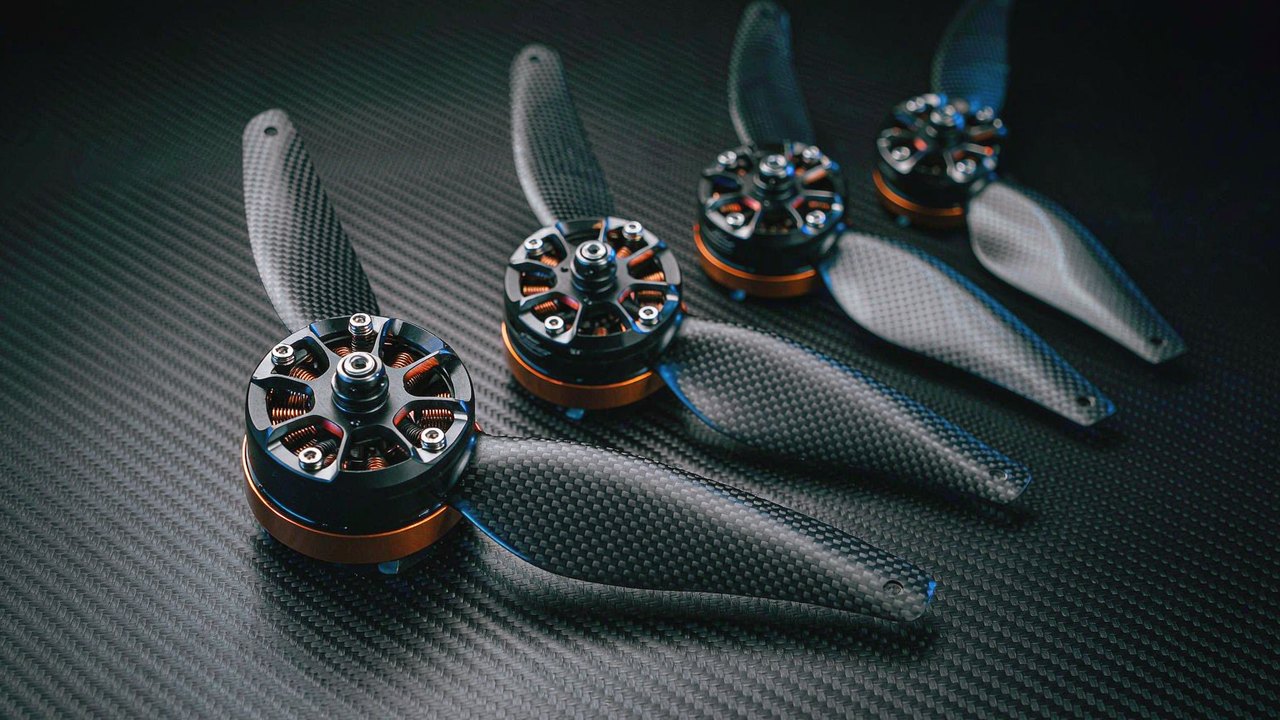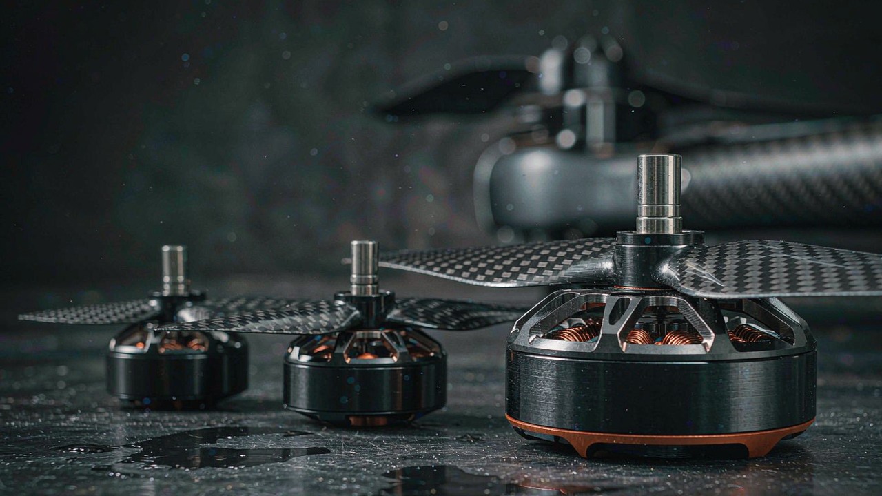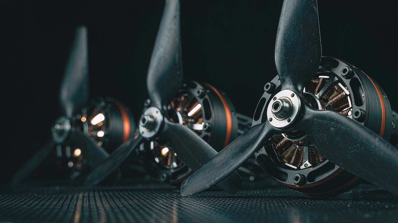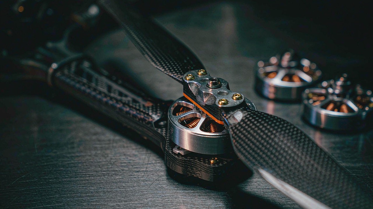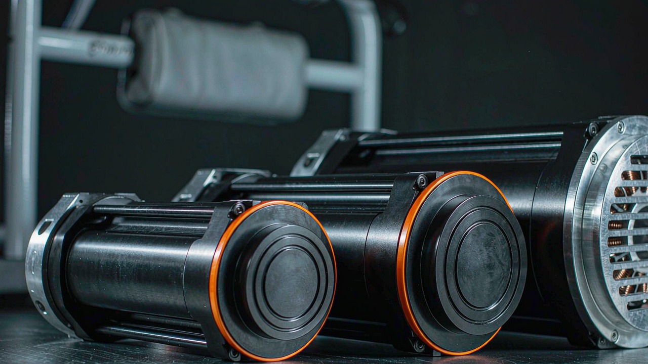
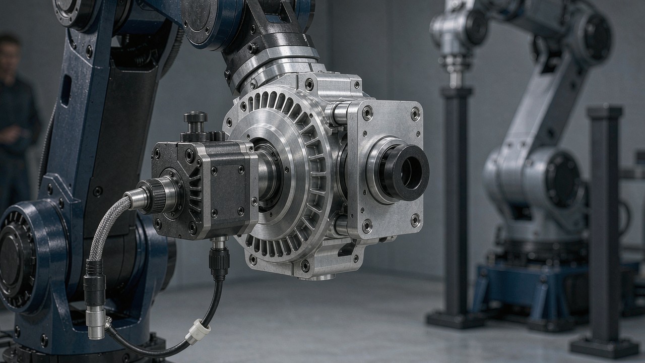
Few components shape what a robot can do more than the joint. It sets the torque available at the output, how fast a limb moves, how much mass hangs at the end of an arm, and how the machine behaves when something pushes back against it. For teams building humanoid legs, collaborative arms, exoskeletons, quadrupeds or wheeled platforms, the decision usually lands on one product class: integrated robotic actuators, where a brushless DC motor, a planetary reducer, feedback electronics and a driver ship as a single sealed unit.
This guide covers how those modules are built, which specifications genuinely change a design decision, and how five of the models currently listed in the ToBMS Robotic Actuators category compare. Every figure below is taken from ToBMS product data or from the manufacturer's published specification - none of it is estimated.
Quick Answer
A robotic actuator is an integrated drive module that combines a BLDC motor, a gearbox, an encoder and motor control electronics in one housing, so the output is a torque-controlled rotating joint rather than a bare motor shaft. Selection usually comes down to four questions: how much torque the joint must deliver at its worst case, how much it can hold continuously, how much backdrivability or stiffness the application needs, and how much mass the upstream joints can afford to carry.
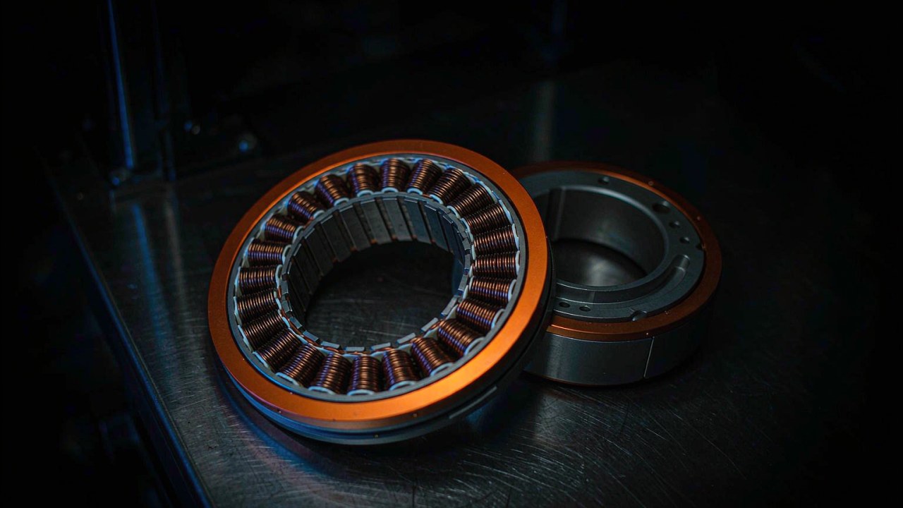
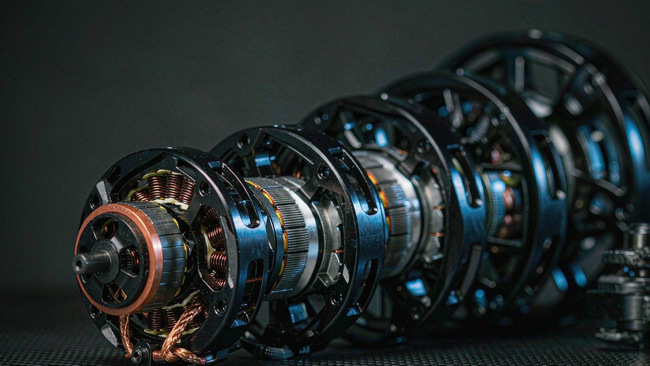
What is inside an integrated robotic actuator
The value of an integrated module is not the motor alone. It is that four subsystems have already been matched, calibrated and sealed together, and the integration work moves from mechanical design to software.
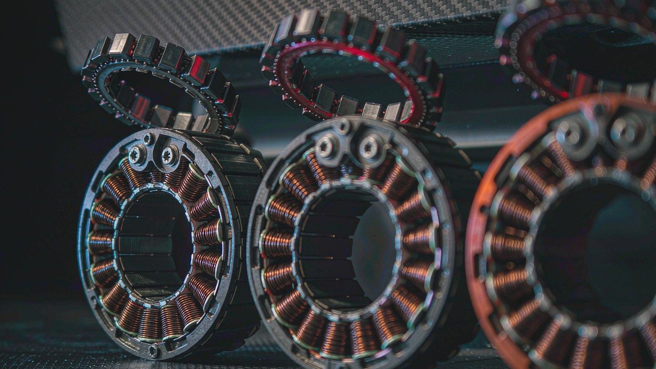
Brushless motor and rotor design
The models in this category use permanent-magnet BLDC motors with 14 to 21 pole pairs, sized for torque density rather than top speed. A higher pole count generally produces more torque per amp and smoother low-speed motion, at the cost of higher electrical frequency at a given speed. KV (the speed constant) is the number most often compared, but it only describes the motor's speed-torque trade-off - it says nothing about the gearbox, the encoder or the achievable torque at the joint.
The reduction stage
A planetary reducer multiplies motor torque and divides output speed. The ratios in the lineup below run from 6:1 to 64:1, and that single number shapes more of a joint's character than any other specification. Multi-stage planetary trains also introduce backlash, which is discussed separately because it becomes a design constraint in its own right for high-ratio modules.
Feedback: encoders and what they measure
These modules use magnetic encoders, either on the output shaft or on both the motor and output shafts. A single output encoder tells the controller where the joint is; a dual setup also gives the motor side the position information it needs for smooth commutation. That difference shows up at low speed, which is exactly where many robotic joints operate.
Driver, control modes and interfaces
Field-oriented control (FOC) electronics are built into the housing. The listed models expose servo-style position/velocity control and MIT-style impedance control over UART or CAN depending on the model. Integration therefore means mounting the module, defining limits, tuning the control loop, and treating the joint as a torque or position axis.
Specifications that actually decide the pick
Datasheets are dense, and not every line carries the same weight for a given robot. The following are the ones that most often change the outcome.
Torque: peak, rated and what they really mean
Peak torque indicates the maximum output torque the manufacturer specifies under defined operating conditions - typically a short-duration limit set by copper losses and magnet temperature rather than by mechanical strength. It is useful for checking transient loads, acceleration peaks and impact events, but it is not the mechanical failure limit of the reducer or the output bearing; if a joint has to survive shock, that has to be confirmed separately with the manufacturer.
Rated torque is the continuous figure: what the module can hold within its thermal limits at the specified ambient and mounting condition. Sizing a joint against peak torque alone is the most common way to end up with a module that runs hot during ordinary duty. Duty cycle, mounting surface and airflow all shift where the real continuous limit falls, so the published number is a starting point, not a guarantee.
Reduction ratio, backdrivability and backlash
Lower reduction ratios generally improve backdrivability and torque transparency, because less gear friction and lower reflected inertia stand between the rotor and the load. Higher ratios generally raise output torque for the same motor and reduce effective backdrivability. Neither relationship is a hard rule: the actual behaviour of a joint depends on gearbox design, friction, backlash, transmission efficiency, motor torque constant, control strategy and the load itself. A low-ratio module driving a heavy inertia through a stiff controller can still feel unyielding, and a high-ratio module with careful torque control can feel far more compliant than its ratio suggests.
Backlash deserves its own check. It is the lost motion at the output when the direction of rotation reverses - the amount the motor turns before the output starts moving again. In multi-stage planetary reducers it accumulates across stages, and it directly affects how repeatable a position command is. For a humanoid leg holding a pose, a collaborative arm doing insertion work, or a rehabilitation device moving a patient's limb, backlash is often the specification that decides whether a module is acceptable, more so than a few percent of extra torque. Two practical points: figures are quoted in arcmin or in degrees, so normalise before comparing (1° = 60 arcmin), and ask whether the number refers to the output shaft, measured unloaded or under load, and before or after run-in.
Supply voltage, current and thermal limits
Most modules here accept 24 V or 48 V and publish separate speed and current figures for each, so the same actuator can behave quite differently depending on the robot's battery architecture. Rated and peak current, together with the rated power figure, define what the driver and the power distribution have to supply. Both torque limits above ultimately trace back to current and heat, which is why thermal behaviour is the constraint that governs real duty.
Output speed
Rated and no-load speed are quoted at the joint output, after reduction. A 64:1 module rated at 23 rpm on 24 V is a positioning joint, not a locomotion joint. When a requirement is expressed as angular velocity, convert it to output rpm before comparing models - it is the fastest way to eliminate half the range.
Mass, inertia and torque-to-weight
Mass matters twice on a robot: it is carried by every joint upstream, and it adds inertia that the joint itself has to accelerate. On a distal joint, 190 g versus 1.4 kg changes the sizing of the whole drivetrain.
Torque-to-weight is only meaningful when the torque basis is stated. A module's peak Nm/kg and rated Nm/kg can differ by a factor of three, and a figure quoted against peak torque says little about continuous capability. Comparing like with like is the only way the number becomes useful.
Encoders, interfaces and control modes
Encoder configuration decides whether the joint can be commanded in torque, position and velocity, and how precisely it can hold a pose; the interface decides whether a given controller can talk to it. Check servo versus MIT mode support, update rate and cable connector type against the rest of the stack before mechanical design freezes.
Five robotic actuators compared
The table covers five of the integrated joint modules currently listed in the Robotic Actuators category, ordered from lightest to heaviest. Torque figures are the manufacturer published values; backlash is not listed because the values held for these models are not unit-consistent across the range.
| Model | Rated Voltage | Rated Torque | Peak Torque | Reduction Ratio | Weight | Envelope |
|---|---|---|---|---|---|---|
| AK40-10 V3.0 KV170 | 24 V | 1.3 Nm | 4.1 Nm | 10:1 | 190 g | Ø53 × 40.2 mm |
| AK60-6 V3.0 KV80 | 24/48 V | 3 Nm | 9 Nm | 6:1 | 380 g | Ø79 × 43 mm |
| AK70-10 KV100 | 24/48 V | 8.3 Nm | 24.8 Nm | 10:1 | 621 g | Ø89 × 50.25 mm |
| AK80-64 KV80 | 24/48 V | 48 Nm | 120 Nm | 64:1 | 850 g | Ø98 × 61.9 mm |
| AKH70-48 V1.0 KV41 | 48 V | 74 Nm | 222 Nm | 48:1 | 1396 g | Ø90 × 81.5 mm |
Rated and peak torque as published by the manufacturer. Envelope gives the outer diameter and length as carried in the manufacturer’s datasheet.
Peak torque spans roughly fifty-fold across this set, from 4.1 Nm to 222 Nm, so these modules are not interchangeable parts. The mass spread, by contrast, is only about seven-fold. That gap is where the interesting engineering sits.
Take the two ends on a like-for-like basis: at 190 g the AK40-10 offers 6.8 Nm/kg continuously and 21.6 Nm/kg at peak, while the 1396 g AKH70-48 reaches 53 Nm/kg rated and 159 Nm/kg peak - roughly eight times the continuous density. But density is not the whole story. The AK80-64 delivers 141 Nm/kg peak at 850 g, which is close to the AKH70-48's 159 Nm/kg while being 546 g lighter; whether the extra torque of the hollow-shaft module is worth that mass depends entirely on whether the joint needs cable pass-through and where it sits in the kinematic chain.
Mapping that range onto a machine usually looks like the following, though the boundary cases depend heavily on lever arm, duty cycle and the stiffness the application needs:
| Joint position | What usually dominates | Modules worth shortlisting |
|---|---|---|
| Wrist, hand, small manipulator | Distal mass - every gram is carried by every upstream joint | AK40-10 V3.0 (190 g), AK60-6 V3.0 (380 g) |
| Elbow, forearm, light leg joint | Balance of speed, torque and encoder quality | AK70-10 KV100 (621 g, 14-bit magnetic encoder) |
| Knee, hip, load-holding axis | Continuous torque against gravity; low output speed is acceptable | AK80-64 KV80 (64:1, 120 Nm peak) |
| Hip, heavy link, cable-routed joint | High output torque plus a hollow bore for harness routing | AKH70-48 V1.0 (222 Nm peak, hollow shaft) |
Light joints: AK40-10 V3.0 and AK60-6 V3.0
The small end of the range covers wrist, forearm and light manipulator joints, where saving mass at the distal end pays back through every upstream joint.
AK40-10 V3.0 KV170: the 190 g end of the range
The AK40-10 V3.0 KV170 is the lightest module in this set: 190 g, a 10:1 stage, 4.1 Nm peak and 1.3 Nm rated torque at 24 V, with 370 rpm rated output and a Ø53 × 40.2 mm envelope. Its ToBMS product overview describes it as an ultralight module intended for dexterous robotic arms and small joint modules, and it is flagged as a new arrival with a 2026 launch date. Rated power is 50 W at 2.7 A rated and 7.3 A peak current, which keeps the driver and cable requirements modest - useful when the harness itself has to squeeze through a small joint.
The manufacturer walks through the AK40-10, AK45-10 and AK45-36, showing how the motor, planetary gearbox and built-in driver are packaged into a single plug-and-play module. It is the clearest short visual answer to why a compact joint module differs from a bare motor plus an external drive.
ToBMS video pageWatch on YouTubeAK60-6 V3.0 KV80: low ratio, faster output
The AK60-6 V3.0 KV80 sits one step up at 380 g with a 6:1 stage and 9 Nm peak / 3 Nm rated torque. On 24 V it is rated at 233 rpm and 320 rpm no-load, rising to 490 and 640 rpm on 48 V, with 74 W rated power. Its ToBMS overview notes the integrated brushless motor, planetary reducer, encoder and drive system, and lists support for both servo and MIT control modes. Because the ratio is the lowest in this comparison, it is generally the more backdrivable choice of the two light modules - though as noted earlier, how much of that transparency reaches the operator still depends on gearbox friction, the control mode and the load.
The SuRover team runs four-wheel steering, point turns and tight-radius navigation on AK60-6 and AK10-9 modules. It is the one clip in this set that shows an AK-series module under continuous mobile duty rather than in a bench demo, which makes it a useful reference for duty-cycle questions.
ToBMS video pageWatch on YouTubeMid-range with 14-bit feedback: AK70-10 KV100
At 621 g with 8.3 Nm rated and 24.8 Nm peak torque, the AK70-10 KV100 sits in the middle of the range and is the module most often cited for exoskeleton and quadruped work. Rated power is 230 W at 7.2 A rated / 23.2 A peak, output speed is 148 rpm on 24 V or 310 rpm on 48 V, and the Ø89 × 50.25 mm body carries 21 pole pairs.
What one encoder means here
CubeMars lists one encoder on the AK70-10 KV100: a 14-bit magnetic unit on the motor side of the 10:1 planetary stage, alongside UART and CAN interfaces. It reads rotor position, so the controller derives joint angle through the 10:1 ratio and lives with the stage's 0.2° backlash. An encoder on the output shaft, which the AK70-10 does not have, would report joint angle directly; that arrangement is worth specifying where a joint moves slowly and must hold position precisely.
A first-time user opens the AK70-10, sets it up and puts it to work in an acrobot. Datasheets rarely show what commissioning actually costs in time and tools; this walkthrough does, which makes it useful before committing the module to a build schedule.
ToBMS video pageWatch on YouTubeHigh-ratio joints: AK80-64 KV80
The AK80-64 KV80 takes the opposite approach. A 64:1 reducer turns a 98 mm, 850 g body into a module rated at 48 Nm continuous and 120 Nm peak, rotating at 23 rpm on 24 V or 48 rpm on 48 V, with 220 W rated power at 7 A rated / 19 A peak.
Why 64:1 changes the joint's behaviour
A higher reduction ratio generally increases output torque for the same motor and reduces effective backdrivability, and at 64:1 the effect is pronounced: little of what happens at the load is felt by the rotor, which is exactly what a hip or knee axis that has to resist gravity for hours needs without a large continuous current draw. It also means the joint is unlikely to be pushed around by hand during setup, and that the ratio itself becomes a source of reflected compliance limits rather than just a torque multiplier. Ratio is one input among several - gearbox design, friction, backlash and the control strategy all contribute to how stiff the joint actually feels in operation.
Université de Sherbrooke uses AK10-9 and AK80-64 modules to deliver controlled stretching movements in a muscular atrophy rehabilitation system. Relevant where the load on the joint is a person rather than a payload, where smoothness and position accuracy matter more than raw torque.
ToBMS video pageWatch on YouTubeHollow-shaft actuators: AKH70-48 V1.0 KV41
Hollow-shaft modules solve a mechanical problem that appears as soon as a robot has more than a few degrees of freedom: cable routing. The AKH70-48 V1.0 KV41 delivers 74 Nm rated and 222 Nm peak torque through a 48:1 planetary stage on 48 V, rated at 28 rpm output (35 rpm no-load) with 6 A rated and 18 A peak current. Its ToBMS data lists FOC drive and a Ke of 2.4 V/krpm. At 1396 g it belongs to leg, hip and heavy-link territory.
Cable routing and harness life
A large bore through the joint axis lets wiring and pneumatic lines pass straight through instead of being looped around the outside of the joint. That solves a packaging problem and a reliability one at the same time: a harness that flexes every time the joint moves is a fatigue failure waiting to happen, and running it through a torsion-free path through the axis removes most of that motion. The trade is mass and, usually, a longer envelope - both of which have to be paid for by the upstream joints.
The manufacturer validates the hollow-shaft module under progressively increasing loads up to 40 kg with full 360° rotation. Short as it is, this is the most direct published evidence of how the 222 Nm peak rating behaves on a real lever arm.
ToBMS video pageWatch on YouTubeWhere robotic actuators are used
On ToBMS these modules appear across a fairly consistent set of applications, and the application decides which specification dominates.
Legged machines and mobile platforms
Humanoid robots, quadruped robots and AGVs load joints dynamically. Impact tolerance, peak torque and torque-to-weight dominate here, and continuous duty against gravity makes thermal behaviour a first-order constraint.
Manipulators and human-interaction devices
Collaborative robot arms, exoskeletons, joint modules and rehabilitation robots live or die by smoothness: backlash, encoder quality and low-speed control matter more than a few extra newton-metres.
Selection checklist
Robotic actuators tend to be specified once and then stay in a design for years, so these checks are worth running before a model reaches the bill of materials.
Duty and torque
- Calculate the worst-case torque at the joint including lever arm and dynamic effects, then check it against peak torque with margin - and confirm with the manufacturer what shock or impact the output stage can survive.
- Estimate continuous torque for the normal duty cycle and check it against rated torque at the intended ambient and mounting condition, since that is the thermal limit rather than a mechanical one.
- Express the speed requirement in output rpm before comparing models; it eliminates candidates quickly.
Mechanics and integration
- Decide whether the joint has to be backdrivable. If it does, shortlist low-ratio modules and confirm the behaviour with the gearbox friction characteristics and control mode, not by ratio alone.
- Set a backlash budget for the axis - especially for position-critical or human-interaction joints - and confirm the manufacturer's figure against their datasheet before comparing.
- Add up distal mass and check the torque-to-weight basis in use (rated or peak). A 300 g saving at the wrist is worth more than the same saving at the hip.
- Check whether the joint needs cable pass-through. If it does, hollow-shaft is not optional.
- Review mounting pattern, connector position and cable routing before mechanical design freezes.
Control, feedback and communications
- Confirm the encoder configuration matches the accuracy and repeatability the application needs, and that the interface supports the control modes the rest of the stack uses.
- Verify the driver's voltage range against the robot's bus, and the rated and peak current against what the power distribution can deliver.
Frequently asked questions
QWhat is the difference between a robotic actuator and a brushless motor?
A brushless motor produces torque at the shaft and needs an external reducer, encoder and drive electronics before it can act as a joint. A robotic actuator integrates those parts in one housing, sealed and calibrated at the factory, so the output is a controllable rotating axis. That shifts engineering effort from mechanical integration to software: the module is mounted, limits are defined and the control loop is tuned. The Robotic Actuators category holds the integrated modules; where only the motor is bought in and the reducer is designed in-house, frameless torque motors are the equivalent starting point.
QHow do I choose between a 6:1, 10:1, 48:1 and 64:1 actuator?
Work backwards from the joint requirement rather than forwards from the motor. The reduction ratio sets output speed for a given motor speed and multiplies torque, so a required output torque and speed pair usually narrows the field to one or two ratios. Then weigh the secondary effects: lower ratios are generally more backdrivable, higher ratios generally give more torque per kilogram but add more gear stages and therefore more backlash. Ratio is only one contributor to how a joint behaves - gearbox design, friction, efficiency, motor torque constant, control strategy and load all play a part.
QCan peak torque be used continuously?
No. Peak torque is the maximum output torque the manufacturer specifies under defined operating conditions, usually for short durations, and it is typically limited by winding and magnet temperature rather than by mechanical strength. Continuous duty should be sized against rated torque within the actuator's thermal limits at the intended ambient temperature and mounting condition. Peak torque is the right figure for checking accelerations, transients and short impact events - not for steady load holding, and not as a stand-in for the module's mechanical failure limit.
QWhat is backlash and how much does it matter in a robot joint?
Backlash is the lost motion at the output when the joint reverses direction - the amount the motor rotates before the output starts moving again. It accumulates across gear stages, so high-ratio multi-stage planetary reducers tend to show more of it than low-ratio units. It matters most where position repeatability is critical: robotic arms doing contact tasks, humanoid legs holding a pose, and rehabilitation devices moving a limb. When comparing figures, normalise the units first (1° = 60 arcmin) and ask the manufacturer whether the value refers to the output shaft, whether it was measured loaded or unloaded, and whether it is a new-unit or post-run-in figure.
QDo I need dual encoders?
Not always, but the case for them is strongest in joints that move slowly and must hold position precisely. An encoder on the output shaft reports the joint angle; an encoder on the motor side provides the rotor position needed for smooth commutation. AK70-10 KV100 carries one motor-side encoder, so the joint angle is derived through the 10:1 stage; where joint angle has to be measured directly, an output-side sensor is usually added.
QWhen is a hollow-shaft actuator worth the extra mass?
When cables, tubing or a through-axis mechanism have to pass the joint rather than around it. A bore through the axis removes the loop of harness outside the joint and the flex fatigue that comes with it, which is a reliability gain as much as a packaging one. The compromise is mass and envelope: the AKH70-48 V1.0 carries 222 Nm peak torque at 1396 g, so the payoff has to be measured against what those extra grams cost the upstream joints.
QWhich control interfaces and modes do these actuators support?
The models listed in this category use field-oriented control with servo-style position and velocity modes and MIT-style impedance control, exposed over UART or CAN depending on the model - the AK70-10, for example, lists both. Because the modes differ in what they assume about the controller, confirm mode support, update rate and connector type against the rest of the stack before the mechanical design is frozen.
Official resources
CubeMars publishes a full product catalogue covering the actuator range, and each model has an official product page with its complete specification, drawing and control documentation - for example the AK70-10 product page and the AKH70-48 product page. The manufacturer remains the source of truth for specifications, drawings, backlash figures and firmware; ToBMS keeps the discovery layer searchable and comparable.
Where to go next
For shortlisting rather than research, three tools on the platform do the work in sequence. Explore the full Robotic Actuators category to see every model and specification side by side, use Select to filter by torque, voltage and mass, then place candidates in Compare Products. Where a joint has to be compliant by design rather than stiff, the Quasi Direct Drive Actuators category is the natural next stop.
Where the joint sits on a legged platform rather than a fixed machine, BLDC Motors for Humanoid Robot: How to Match Torque, Speed and Size repeats the same three axes from ankle through hip.The short version: match peak torque to the worst case, rated torque to the duty cycle within thermal limits, ratio and backlash to the behaviour the joint needs, and mass to the joint's position in the kinematic chain. Everything else - connectors, firmware modes, bore size - is downstream of those four decisions.