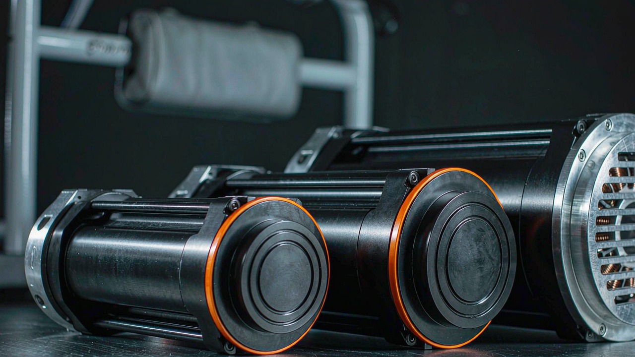
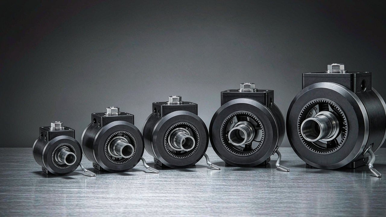
A joint module is an entire robot axis delivered as one part: a brushless motor, a reduction stage, feedback electronics and - on most modern units - the driver, sealed into a housing that bolts straight between two links. Choosing one is rarely about finding the highest torque number. It is about how much torque the axis can hold continuously without cooking itself, how fast the link can move, how much mass sits at the end of the limb, how the cables leave the housing, and how much play sits between the gearbox input and the output flange. This guide works through five CubeMars modules that span 190 g to 1.4 kg and 4.1 Nm to 222 Nm of peak torque, and explains which specification actually decides the choice at each joint position.
The five units below all belong to the same family idea - a BLDC motor driving a planetary stage with integrated position feedback - yet they are built for different jobs. Three run on a 24 V bus with 10:1 and 36:1 reductions; two run on 48 V with 16:1 and 48:1 reductions and a hollow output shaft. Reading them together is the fastest way to understand what a joint module actually is, because the trade-offs show up as numbers rather than as marketing categories. Every figure in this article comes from the ToBMS product records or the manufacturer's published specification; nothing here is estimated, and where a value is not recorded it is marked as such rather than filled in.
Quick answer
A joint module is specified by working backwards from the joint, not forwards from the motor. Establish the worst-case torque the axis must produce, the angular velocity the link needs, the mass budget at that position in the kinematic chain, and the diameter the mechanism can accept - then pick the lightest module whose continuous (rated) torque covers the real duty cycle and whose peak torque covers the transient, with the bus voltage chosen to suit the rest of the robot's power system.
Applied to these five modules, that logic produces a simple ladder. The 190 g AK40-10 V3.0 is the distal-joint unit - hands, wrists, small gimbals and light arm segments where mass at the end of a lever is the dominant cost. The 262 g AK45-10 V3.0 covers light-to-medium joints on the same 24 V bus with nearly double the peak torque. The 349 g AK45-36 V3.0 steps up to 24 Nm peak by trading speed for reduction, which makes it a natural fit for an elbow or a knee on a mid-size arm. The 879 g AKH70-16 V1.0 and 1.4 kg AKH70-48 V1.0 move to 48 V, a 90 mm envelope and a hollow shaft, which puts them in hip, base and heavy-load territory where cable routing through the axis matters as much as torque does.
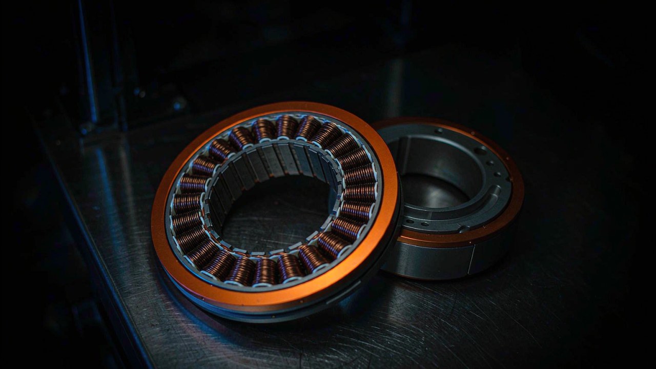
What a joint module is built from
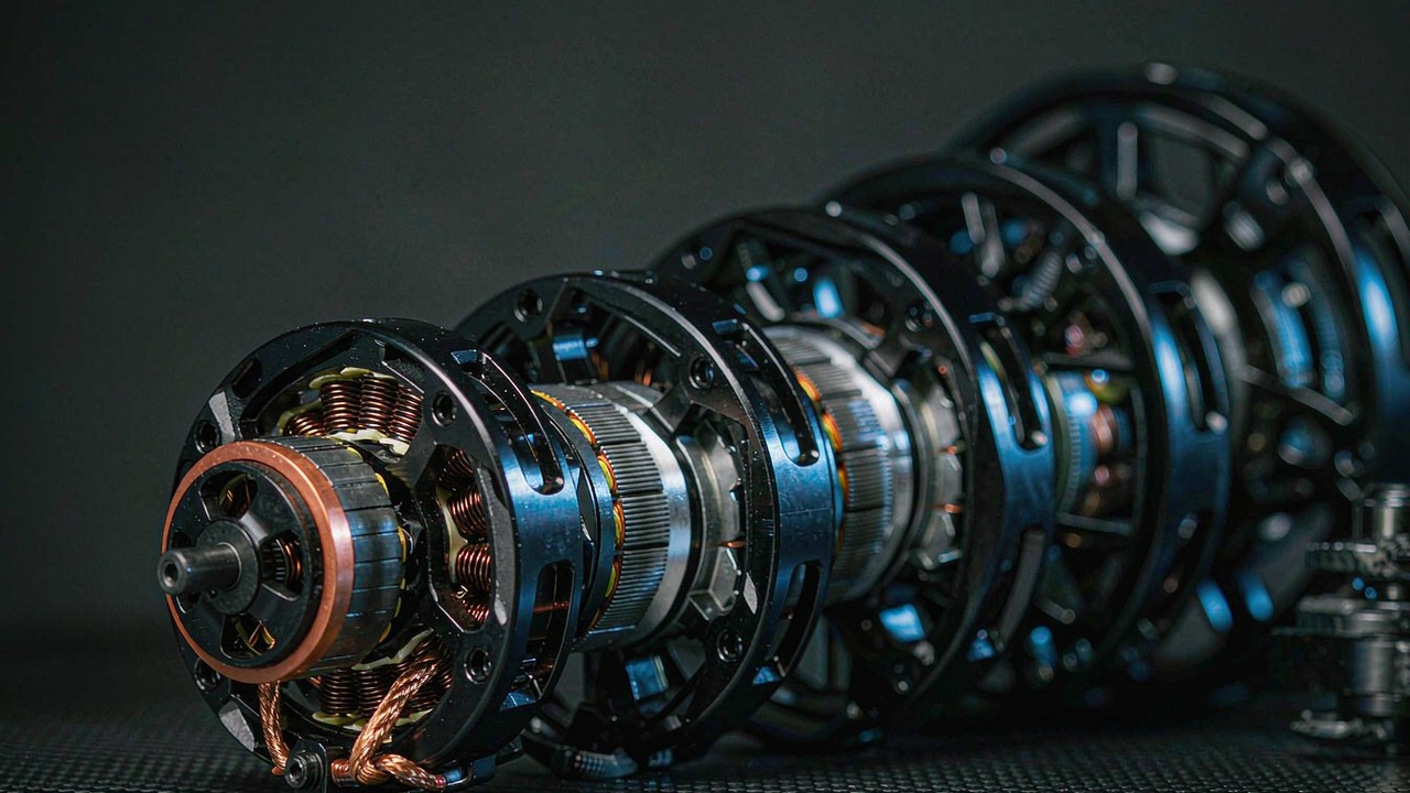
The parts are not exotic. What makes a joint module different from a motor plus a gearbox bought separately is that the interfaces between those parts are already resolved - the rotor is supported by the gearbox input bearing, the encoder is mounted to a datum that survives the gearbox load path, and the housing closes the whole assembly. That is the value being bought.
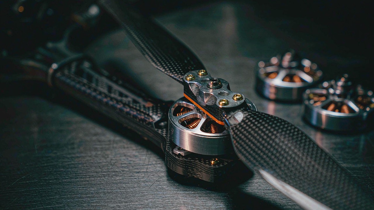
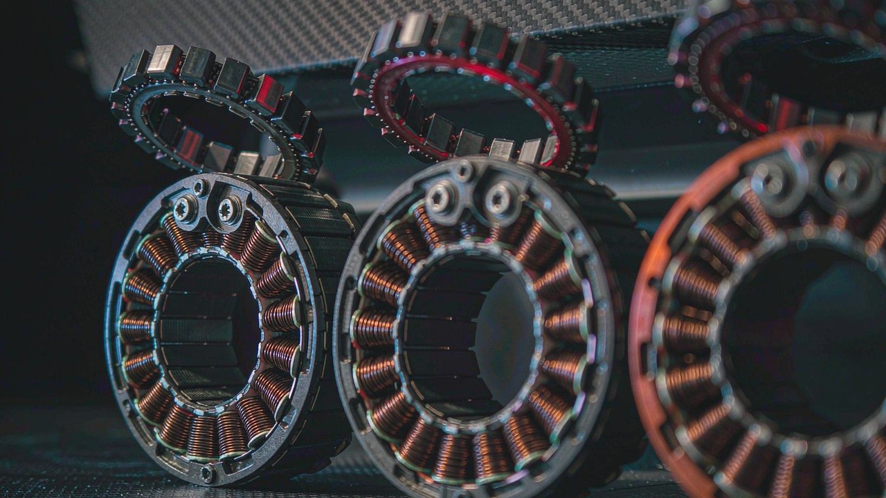
The motor
All five units use a brushless DC outrunner motor, and the figure that separates them at this level is KV - the motor's speed constant in rpm per volt. The AK40-10 V3.0 carries a KV170 winding, the AK45-10 V3.0 a KV75, the AK45-36 V3.0 a KV80, and both AKH70 modules a KV41. A high-KV winding delivers more speed per volt with less torque per amp; a low-KV winding does the opposite. That single choice cascades through the whole design, and it is the reason the smallest module in this group has the highest KV and the largest has the lowest. Both AKH70 modules also list 21 pole pairs against 14 for the three AK units, which raises the electrical frequency the driver has to commutate at any given mechanical speed.
The reduction stage
Each module integrates a planetary gearbox: 10:1 on the AK40-10 and AK45-10, 36:1 on the AK45-36, 16:1 and 48:1 on the two AKH70 units. The stage converts the motor's high-speed, low-torque output into the joint's low-speed, high-torque output, and it also decides how much of the load the link can push back into the motor. A 10:1 stage generally leaves the joint easier to back-drive, which is useful for compliant control and for hand-guiding a collaborative arm; a 48:1 stage generally multiplies torque further and reduces back-drivability, but the actual outcome depends on gearbox efficiency, the motor's torque constant and how much reflected inertia the link presents - ratio alone does not settle it.
Feedback and drive electronics
Position feedback is what turns a motor and gearbox into a servo joint. The ToBMS overview for the AK40-10 V3.0 describes the unit as integrating a BLDC motor, a 10:1 planetary gearbox and a driver, and both AKH70 modules list FOC (field-oriented control) as the driving method. Whether the controller board is physically inside the module or supplied alongside it varies by family, so confirm the exact delivery configuration with the manufacturer before the wiring harness is designed. The same applies to the encoder interface: resolution, protocol and whether the sensor is absolute or incremental are all decisions that ripple into the robot's control architecture.
What the integrator still has to supply
A joint module is not a finished axis. The mounting interface on both sides, the cable routing and strain relief, the thermal path out of the housing, the power supply and its current headroom, and the safety limits enforced in the controller are all still the integrator's responsibility. The gain is that the mechanical and magnetic design inside the housing has already been matched and tested as a unit.
The five numbers that decide the pick
Specification tables for joint modules are long, but only a handful of entries change a design decision. These are the five that matter, and how to read each one honestly.
Peak torque is not a working torque
Peak torque is the output a module can produce briefly - during an acceleration burst, an impact, or a torque spike at the end of a motion. It is a short-duration figure and it is not the mechanical limit of the gearbox, nor the load the joint can hold indefinitely. Designing to peak torque as if it were continuous is the most common way to destroy a joint module, because the limitation that arrives first is thermal rather than mechanical. Treat peak as headroom for transients and size the gearbox and structure against it separately.
Rated torque is a thermal statement
Rated torque is what the module should be able to sustain within its thermal limits, and it is the number that should be compared against the real duty cycle rather than against a single worst case. The AKH70-48 V1.0 lists 74 Nm rated against 222 Nm peak; the AK40-10 V3.0 lists 1.3 Nm against 4.1 Nm. Those two pairs are not the same kind of statement, and the ratio between them is not a margin to be spent - it is the difference between a temperature rise the housing can shed and one it cannot. Rated torque also depends on ambient temperature, mounting and duty, so a continuous rating taken in free air is optimistic for a module buried inside a limb.
Output speed, not motor speed
The speed that matters is the speed of the output flange, and it is already reduced by the gearbox. The AK40-10 V3.0 is listed at 370 rpm rated with a 435 rpm no-load figure; the AK45-10 V3.0 at 120 and 180 rpm; the AK45-36 V3.0 at 40 and 52 rpm; the AKH70-16 V1.0 at 90 and 105 rpm; the AKH70-48 V1.0 at 28 and 35 rpm. Converted to joint terms, 370 rpm is 2220 degrees per second and 28 rpm is 168 degrees per second, which is the difference between a wrist that can flick and a hip that swings slowly. Check the required link velocity at the bus voltage actually available, because a module quoted at one voltage does not deliver the same no-load speed at another.
Gear ratio sets the torque-speed balance
Ratio is the most visible number in the table and the easiest to misread, because it is a description of a trade rather than a measure of quality. A 48:1 stage produces more output torque per amp and a slower output than a 10:1 stage built around a comparable motor, and it changes the way the joint feels when something external pushes the link. Comparing two modules on ratio alone hides the fact that the motor windings differ too - the AKH70 modules run KV41 against KV75 and KV80 on the AK45 units, so the two effects compound.
Mass, envelope and torque density
At a distal joint, mass is the parameter that dominates, because everything upstream has to carry it through the whole motion envelope. Torque density in Nm per kilogram makes the comparison explicit, and it has to be quoted separately for rated and peak output: the AK40-10 V3.0 works out at about 6.8 Nm/kg rated and 21.6 Nm/kg peak; the AK45-10 V3.0 at 9.5 and 26.7; the AK45-36 V3.0 at 22.9 and 68.8; the AKH70-16 V1.0 at 29.6 and 88.7; and the AKH70-48 V1.0 at 53 and 159. Those figures are derived from the mass and torque values in each product record, and they confirm what the ladder above suggests - the heavier modules earn their mass back in torque per kilogram. Envelope is the companion constraint: a 53 mm diameter body fits inside an arm link that a 90 mm module cannot enter at all, whatever the torque figure says.
Backlash and what it does to a joint
Backlash is the lost motion between the gearbox input and the output flange, and on a position-controlled joint it appears as a small region where the commanded angle changes without the output moving. It matters most where the joint reverses direction under load, and it accumulates across stages in multi-stage planetary designs. Each product record in this group carries a backlash value - 0.3 on the AK40-10 V3.0 and AK45-10 V3.0, 0.2 on the AK45-36 V3.0 and both AKH70 modules - treat those numbers as indicative and confirm the figure on the manufacturer's datasheet before designing to it.
Five CubeMars joint modules compared
The table below collects the five modules ordered by mass, which also orders them by output torque. Torque values are manufacturer-published figures as recorded in the ToBMS product data, and every model also offers KV variants outside this selection.
| Model | Rated Voltage | Reduction Ratio | Rated Torque | Peak Torque | Weight | Envelope |
|---|---|---|---|---|---|---|
| AK40-10 V3.0 KV170 | 24 V | 10:1 | 1.3 Nm | 4.1 Nm | 190 g | Ø53 × 40.2 mm |
| AK45-10 V3.0 KV75 | 24 V | 10:1 | 2.5 Nm | 7 Nm | 262 g | Ø53 × 45.2 mm |
| AK45-36 V3.0 KV80 | 24 V | 36:1 | 8 Nm | 24 Nm | 349 g | Ø55 × 56.5 mm |
| AKH70-16 V1.0 KV41 | 48 V | 16:1 | 26 Nm | 78 Nm | 879 g | Ø90 × 60.5 mm |
| AKH70-48 V1.0 KV41 | 48 V | 48:1 | 74 Nm | 222 Nm | 1396 g | Ø90 × 81.5 mm |
All five modules are listed in the ToBMS Robotic Actuators category. Torque, mass and envelope values are taken from each product record; local units are as published (1396 g is recorded as 1396). A rated power figure for the two AKH70 modules sits with the manufacturer's datasheet, so none is quoted here - check that datasheet if the figure is needed for a power budget.
Two patterns stand out. The first is that mass grows faster than the reduction ratio but slower than peak torque: going from the 349 g AK45-36 V3.0 to the 1.4 kg AKH70-48 V1.0 multiplies mass by four and peak torque by more than nine. The second is that the supply voltage separates the group cleanly into two halves - the three AK modules run on 24 V and the two AKH70 modules on 48 V - which usually means two power rails and two driver families on a single robot unless the whole platform is standardised on one bus.
Both AKH70 modules share the same 90 mm diameter, the same KV41 winding, the same 21 pole pairs and the same backlash figure, and differ almost entirely in reduction stage and stack length: 16:1 in a 60.5 mm body at 879 g, or 48:1 in an 81.5 mm body at 1.4 kg. That is about as clean a demonstration of what a gear ratio costs as a catalogue gets, and it means the two can substitute for each other in the same mechanical envelope if the speed and torque requirement changes.
Five joint modules, five jobs
The ordering above is by mass and torque. The ordering below is by the job each module is suited to, which is the way the choice is actually made.
AK40-10 V3.0 KV170 - hands, wrists and distal axes
At 190 g with a 53 mm diameter and 40.2 mm length, this is the module to reach for when the mass hangs at the end of a lever. It produces 4.1 Nm peak and 1.3 Nm rated through a 10:1 stage, on a 24 V bus, with a rated speed of 370 rpm - fast enough for a wrist or a finger group to reposition quickly. Its ToBMS entry describes it as suited to dexterous robot work, and the application links attached to the record point at joint module, rehabilitation robot, collaborative arm and humanoid use. The limit to keep in view is rated torque: 1.3 Nm continuous is a modest budget, so a distal axis that holds a payload statically still needs a duty analysis rather than a peak-torque check.
AK45-10 V3.0 KV75 - the light mid-range
Same 24 V bus, same 10:1 ratio, same 53 mm diameter - but 45.2 mm long, 262 g, and 7 Nm peak against 2.5 Nm rated. The KV75 winding cuts the rated speed to 120 rpm and the no-load speed to 180 rpm in exchange for that torque, which is exactly the trade a light arm segment wants. The record lists 39 W rated power, making it the more efficient of the two 10:1 units in this group at its rated operating point, and its overview points at compact robot joints and rehabilitation equipment. Against the AK40-10 it is the natural step when the distal joint turns out to need more holding torque than the smaller unit can sustain.
AK45-36 V3.0 KV80 - the low-speed, high-torque step
The first real change of character in the ladder. A 36:1 stage turns the same 24 V family into an 8 Nm rated, 24 Nm peak unit at 40 rpm rated and 52 rpm no-load - 240 degrees per second at the output, which is a deliberate, load-holding joint rather than a quick one. It stays at 349 g and grows only to 55 mm diameter and 56.5 mm in length, so it still fits inside a link. Its ToBMS overview describes it as engineered for joint modules needing high reduction, and the record carries a main-product flag, which reflects how central this torque-per-gram point is to the range. The cost of the ratio is speed and back-drivability: at 36:1 the joint will feel considerably stiffer to an external push than either 10:1 unit.
The manufacturer runs the AK40-10, AK45-10 and AK45-36 side by side, which is the clearest way to judge how the 10:1 and 36:1 stages differ in output speed and how the three envelopes compare in the hand.
ToBMS video pageWatch on YouTubeAKH70-16 V1.0 KV41 - torque with a cable bore
The jump to 48 V and a 90 mm body buys 26 Nm rated and 78 Nm peak at 90 rpm rated - 540 degrees per second, the second-fastest output in this group despite the largest diameter. The KV41 winding is the low-speed, high-torque end of the winding range, and at 21 pole pairs the drive has to commutate at a higher electrical frequency than the AK units for the same output speed. The hollow shaft is the structural feature that changes how a robot is built: power and sensor cables can pass along the axis of rotation instead of looping around the joint, which removes a moving service loop from every articulation. ToBMS records for this module do not include a bore diameter, so obtain the mechanical drawing from the manufacturer before planning the harness. Its overview positions it at quadruped knees, robotic arm joints and wheeled platforms, and the associated applications span humanoid, exoskeleton and AGV work.
AKH70-48 V1.0 KV41 - the heavy joint
The largest module here trades nearly all of its speed for torque: a 48:1 stage on the same KV41 motor and 48 V bus yields 74 Nm rated and 222 Nm peak at 28 rpm rated, or 168 degrees per second. In a 90 mm diameter, 81.5 mm long, 1.4 kg package, that is 53 Nm/kg rated and 159 Nm/kg peak - the highest torque density in the group by a wide margin, and roughly twice the rated density of the AKH70-16. Rated current is 6 A against 18 A peak, so the driver and the power distribution have to be sized for the transient while the continuous thermal path has to carry only the lower figure. Its ToBMS overview names heavy legged robots and AGV work, and the applications attached to the record include humanoid, quadruped and exoskeleton as well as AGV. Whether a 48:1 ratio leaves the joint acceptably back-drivable for a given controller is a question to answer with the manufacturer, because it depends on efficiency and reflected inertia rather than on ratio alone.
A 40 kg mass is rotated a full turn by the module, which is the most direct evidence available in the video library for how the 48:1 stage behaves with a real load hanging on the output flange rather than on a test bench.
ToBMS video pageWatch on YouTubeWhere these joint modules get used
The same five modules appear across very different machines, and the pattern of which one is chosen is consistent enough to be useful as a starting hypothesis.
Humanoid arms and legs
A humanoid concentrates every one of these trade-offs in one machine. Arm joints sit at the end of a kinematic chain and want the lightest module that can hold the payload, which points at the 190 g and 262 g units; hips and knees carry the whole body, which points at the 48 V modules. See BLDC motors for humanoid robots for the broader selection view.
Quadruped knees and hips
Legged robots load joints with ground impact as well as gravity, so peak torque headroom and structural stiffness dominate. The 879 g AKH70-16 V1.0 and the 1.4 kg AKH70-48 V1.0 are the recorded matches for quadruped robot joints, and the hollow shaft simplifies the harness on a leg that has to fold.
Collaborative robot arms
A cobot arm has to be back-drivable enough to be guided by hand and light enough to be safe next to a person, which favours the lower ratios. The 10:1 units are the recorded fit for collaborative robot arms, with the 36:1 module taking the joints that need to hold position rather than comply.
Exoskeletons and rehabilitation robots
These machines are worn or closely coupled to a person, so mass at the limb and the feel of the joint both matter more than peak output. Both AKH70 modules record exoskeleton and rehabilitation applications, and the lighter AK modules appear across rehabilitation robot and exoskeleton entries. Three CubeMars QDD actuators intended for this duty are compared side by side in Exoskeleton Actuators: Three CubeMars QDD Actuators from 260 g to 1.4 kg.
AGVs and wheeled platforms
A wheeled drive joint cares less about back-drivability and more about torque per kilogram and the ability to pass a cable through the axis for a wheel that steers continuously. The AKH70 modules carry AGV application links, and BLDC motors for AGVs collects the wider set.
Selection checklist
Joint modules are usually specified before the rest of the mechanism is frozen, so these checks are worth running early rather than after the geometry is settled.
Duty and torque
- Calculate the worst-case output torque including lever arm, payload and dynamic effects, and check it against peak torque - then confirm separately with the manufacturer what the gearbox and output bearing can survive in shock, because peak is a short-duration figure rather than a mechanical limit.
- Estimate the continuous torque for the real duty cycle and compare it to rated torque, remembering that the rating is a thermal statement and that mounting and ambient conditions change it.
- Convert the required link velocity into output rpm at the bus voltage actually used, taking the no-load figure as an upper bound and the rated figure for sizing.
Mechanics and cabling
- Check the envelope against the link geometry before comparing torque: a 90 mm body and a 53 mm body are not interchangeable however the numbers read.
- Decide the cable route early - around the joint, or through a hollow shaft where the module offers one. ToBMS records do not list bore diameters, so confirm the drawing with the manufacturer.
- Plan the mounting interface and the load path on both faces, and confirm backlash and its unit against the manufacturer's datasheet before designing a position loop around it.
Control and integration
- Confirm what ships inside the module - motor, reducer, encoder and driver are not guaranteed to arrive together - and match the feedback protocol to the controller.
- Match pole pairs and maximum speed against the drive's commutation capability; 21 pole pairs at high output speed raises the electrical frequency considerably.
- Size the power supply and driver for peak current while sizing the thermal path for rated current, and keep the two budgets separate.
Frequently asked questions
QWhat exactly is included in a joint module?
At minimum a brushless motor, a reduction stage and position feedback, packaged in a housing with mounting interfaces on both faces. Driver electronics are frequently integrated as well - the ToBMS overview for the AK40-10 V3.0 states that a driver is included, and both AKH70 modules list FOC as the driving method. What a module never includes is the surrounding work: mounting structure, cable management, thermal path, power supply and the safety limits configured in the controller.
QCan a joint module hold its peak torque continuously?
No. Peak torque is a short-duration output for acceleration bursts and transients, and it is not the mechanical limit of the gearbox. Continuous operation is bounded by rated torque, which is a thermal statement about temperature rise within the housing under stated conditions. A joint that holds a static payload must be checked against rated torque for the whole duty cycle, not against peak.
QWhy do the AKH70 modules use 48 V while the AK series uses 24 V?
Higher bus voltage allows the same power with less current, and torque at the output is produced through a 48:1 or 16:1 stage with a KV41 winding. In practice the split matters more for the robot than for the module: mixing 24 V and 48 V modules means two power rails, two driver families and two sets of safety limits unless the platform is standardised on one bus. Both AKH70-48 V1.0 and AKH70-16 V1.0 are listed at 48 V.
QWhat does a hollow shaft actually buy on a robot joint?
Cable routing through the axis of rotation. On a standard joint, every sensor and power cable has to cross a moving gap, usually as a service loop that has to survive millions of flex cycles. A hollow output shaft lets the harness run straight through the centre of the joint, which shortens the run and removes the loop from the mechanical design. It also changes the bearing and sealing arrangement, so it is a structural decision rather than an accessory.
QHow much backlash should I expect from these modules?
Each record in this group lists a value - 0.3 on the two 10:1 units and 0.2 on the 36:1 and both AKH70 modules - the figures should be treated as indicative. Confirm the manufacturer's figure, and at what load, before designing a position loop or a stiffness claim around the number.
QCan 10:1 and 48:1 modules be used on the same robot?
Yes, and it is common - distal joints want lower ratios and lighter modules while proximal joints want reduction and torque. The practical constraints are the power bus (the 10:1 units here are 24 V, the 48:1 unit is 48 V) and the control model, because a highly reduced joint and a near-direct-drive joint respond quite differently to torque commands and to external forces. Plan the control architecture around that difference rather than treating every axis as identical.
QWhich module should a first leg prototype start with?
The most common starting point for a mid-size legged prototype is a 48 V module with a hollow shaft, because legs need torque, cable pass-through and enough stiffness to survive ground contact; the AKH70-16 V1.0 at 26 Nm rated and 90 rpm sits between the very slow high-torque option and the light 24 V units. Beyond the torque budget, the deciding factor is usually whether the design can accommodate a 90 mm envelope - if it cannot, the 55 mm AK45-36 V3.0 is the largest module that will fit.
Official resources
CubeMars publishes a specification page for every module, and those pages - not third-party summaries - are the reference for thermal ratings, encoder details, mechanical drawings and current firmware. The manufacturer pages for the units discussed here are the AK40-10 V3.0 KV170, the AK45-10 V3.0 KV75, the AK45-36 V3.0 KV80, the AKH70-16 V1.0 KV41 and the AKH70-48 V1.0 KV41. Where a ToBMS record is silent - rated power for the AKH70 modules, bore diameter, backlash unit - the manufacturer page or the datasheet is the place to close the gap.
Where to go next
If the goal is to shortlist rather than to read, three tools do the work in sequence: explore every model in the Robotic Actuators category, narrow candidates by torque, voltage and mass in Select, then set them against each other in Compare Products. Where the joint should be integrated into the machine rather than delivered sealed, the Frameless Torque Motors category is the alternative route, and the Robotic Actuators: How to Choose the Right Integrated Actuator for Robot Joints covers the wider actuator range that sits around these five modules.
For the leg and arm joints of a humanoid platform, BLDC Motors for Humanoid Robot: How to Match Torque, Speed and Size applies the same envelope-first sequence across eight actuators.The short version: fix the envelope from the link geometry, choose the reduction from the required output speed and torque, size rated torque against the duty cycle within thermal limits and peak torque against the transient case, then decide the bus voltage and cable route before the mechanism is frozen. Everything else about a joint module follows from those four.