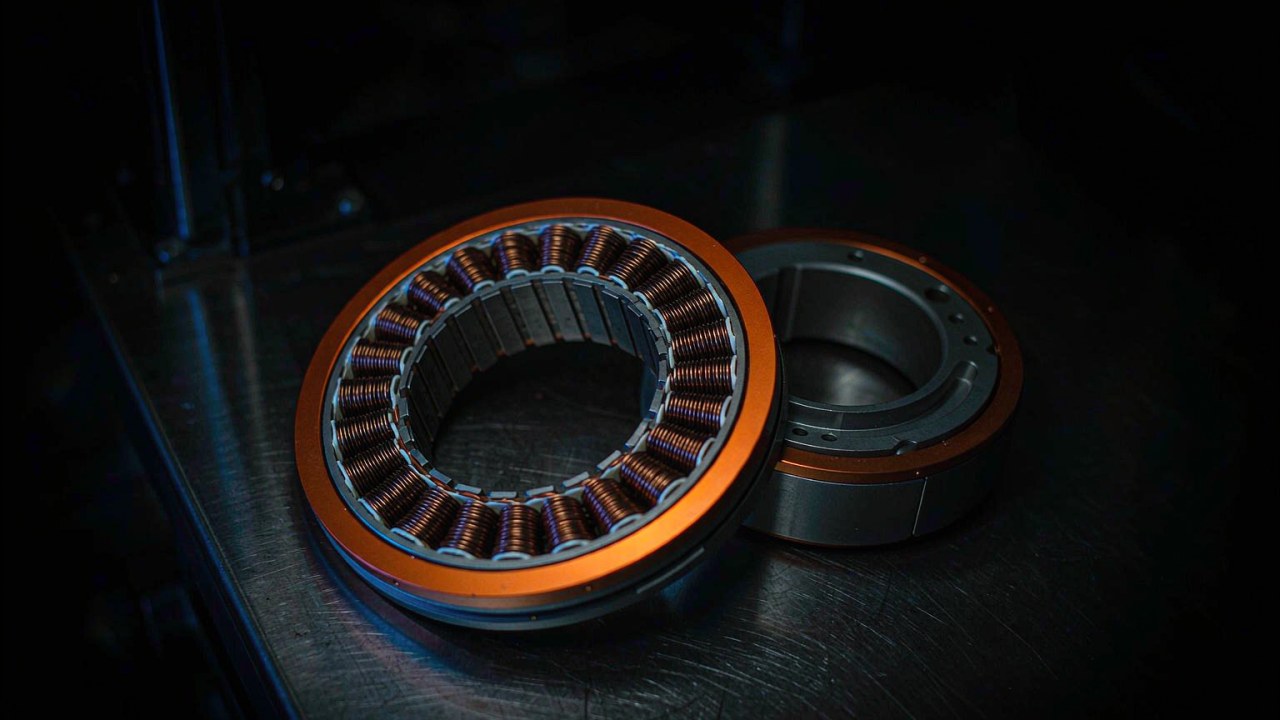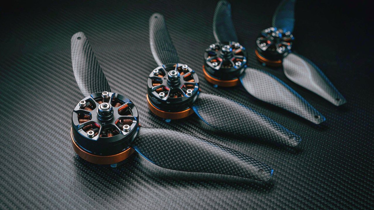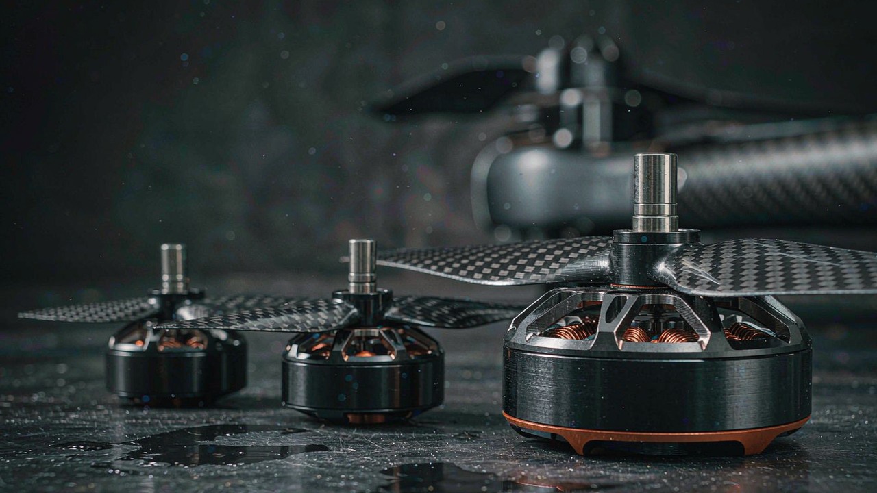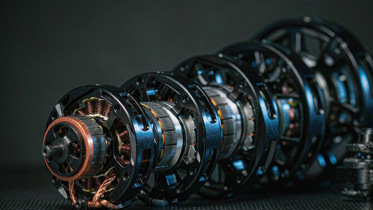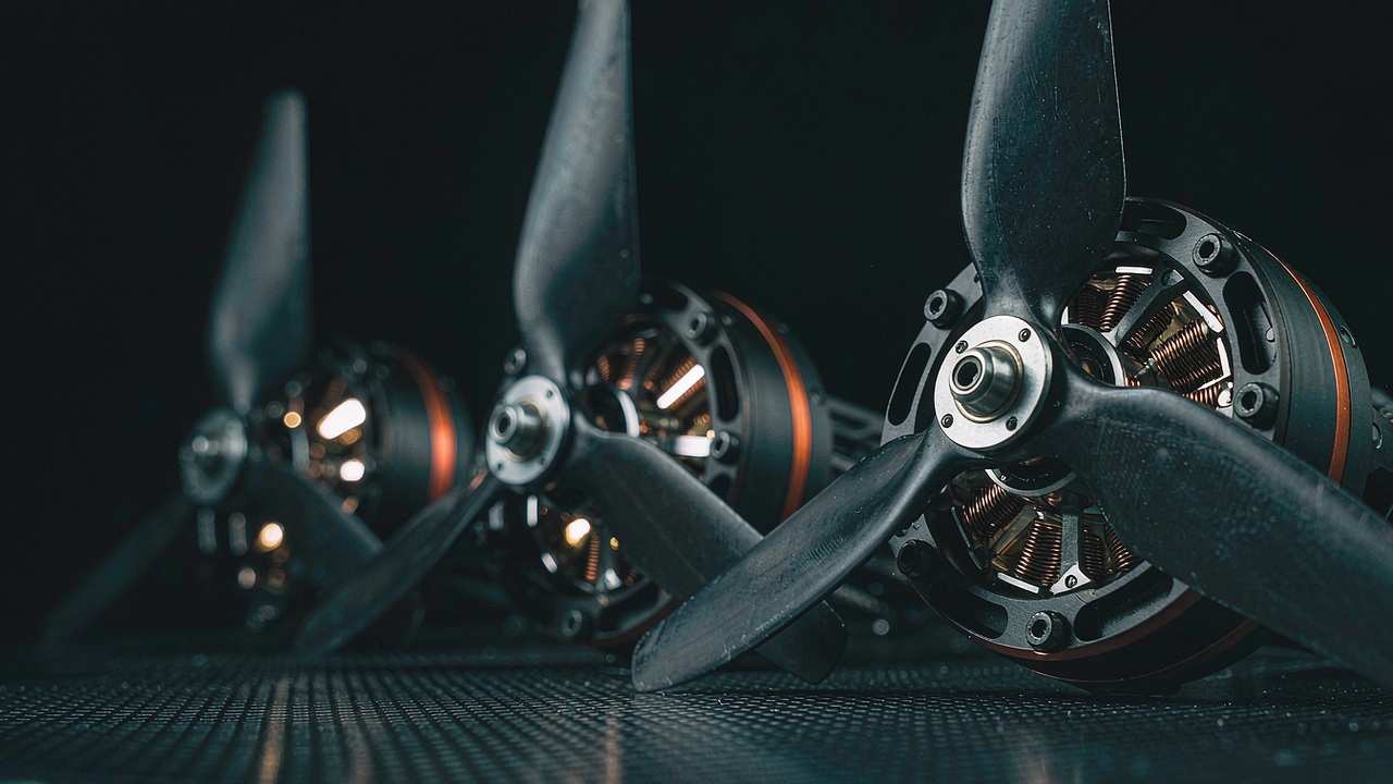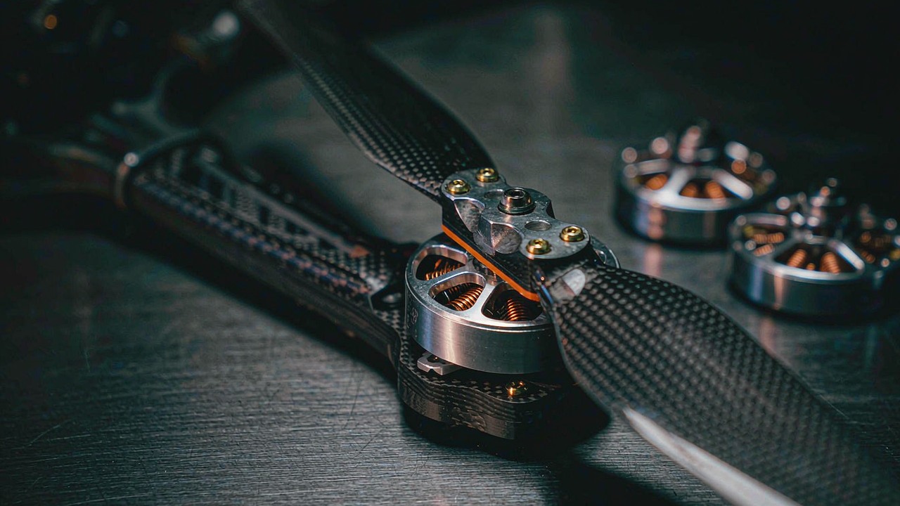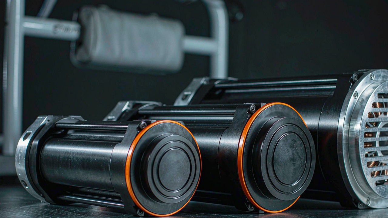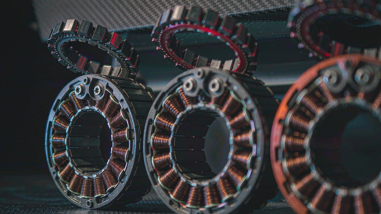
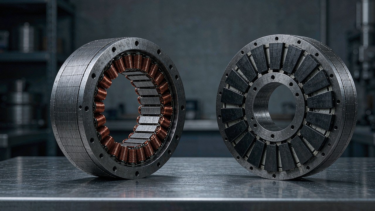
A frameless torque motor is what is left of a brushless motor after the housing, shaft, bearings and end caps are removed: a stator with wound copper coils and a rotor carrying the magnets, sold as two parts that the machine builder integrates into their own structure. For robot joints that decision is deliberate, not a cost shortcut - the motor becomes part of the joint rather than an object bolted onto it, and the bearing arrangement, thermal path and cable routing are designed around the kinematics instead of being inherited from a catalogue housing.
This guide covers how frameless motors are built, which specifications actually change a design decision, and how the twelve models currently listed in the ToBMS Frameless Torque Motors category compare. Every figure below is taken from ToBMS product data or the manufacturer's published specification - none of it is estimated.
Quick Answer
A frameless torque motor is a stator-and-rotor kit with no housing, no shaft and no bearings, purchased so that the machine designer supplies those parts themselves. It is selected for three reasons: it removes the mass and axial length of a conventional motor housing from the joint, it lets the rotor run on the joint's own bearings so there is no second bearing pair in the load path, and it gives access to a large bore for cable routing. The trade is integration work - bearing support, thermal path, rotor retention and feedback all become part of the joint design rather than a purchase order.
What is inside a frameless torque motor
Two components, and nothing else. Everything that would normally be assembled around them is left to the integrator.
The stator
The stator is a laminated steel core with copper windings, terminated on flying leads or a connector block. It has a defined outer diameter and mounting provision - typically a flange pattern or a press fit - but no enclosure. In a robot joint the stator is usually clamped into a machined housing that doubles as the thermal path, which is why mounting surface and interface material matter more here than on a cased motor: the winding temperature limit is reached sooner when heat has nowhere to go.
The rotor
The rotor is a steel or aluminium hub carrying the permanent magnets, with a bore sized either for a press fit onto the joint shaft or for a direct interface with the reducer input. Nothing retains it except the joint's own bearings, so runout, axial location and rotor balance are the designer's responsibility. Getting that wrong shows up as vibration, cogging and encoder noise rather than as a failed part.
Inner rotor and outer rotor layouts
Two arrangements appear in this category. Inner-rotor machines - the RI series - keep the magnets on a shaft inside the stator, which usually gives a longer, smaller-diameter package. Outer-rotor machines such as the RO60, RO80 and RO100 put the magnets on a bell that rotates around the stator, which generally favours a larger diameter, shorter stack and a different inertia distribution. Neither is universally better; the choice follows the joint envelope and how much inertia the control loop can tolerate.
Feedback: Hall sensors or none
Frameless kits rarely carry a full encoder, because the resolution needed at the joint output depends on the joint, not the motor. What varies in this range is Hall effect sensing: the RO40 and RO50 Lite models are listed without Hall sensors, while the RO60, RO80 and RO100 Standard models include them. Without Hall sensors, commutation relies on an external encoder or sensorless start-up, which is entirely workable but has to be planned for in the drive configuration. This is the single specification most often missed when a frameless motor is selected on torque and mass alone.
Specifications that actually decide the pick
Frameless product pages look compact, but the same handful of figures decides most projects.
Torque: rated, peak and what each one promises
Peak torque is the maximum output torque the manufacturer specifies under defined operating conditions, and for a frameless motor it is usually limited by winding temperature and magnet demagnetisation margins rather than by mechanical strength. It is the right figure for checking acceleration peaks and short transients, and the wrong figure for load holding or for estimating when something will break - the mechanical limit of the rotor and the joint's bearings has to be confirmed separately.
Rated torque is the continuous figure the motor can hold within its thermal limits at a stated ambient and mounting condition. On a frameless motor those two conditions carry more weight: a stator clamped into an aluminium housing sheds heat very differently from one running in still air on a bench. The published rated torque is a starting point for a joint that will be judged on its own cooling design.
KV, Ke and supply voltage
KV is the speed constant - how fast the motor turns per volt of applied drive - and it is the number that links the joint's required output speed to the bus voltage. Several of the larger models here are listed with ratings at two or three voltages: the RI50 is specified at 24, 36 and 48 V with correspondingly different rated and no-load speeds, so the same hardware covers a range of joints depending on the robot's battery architecture. Where a frameless motor is being matched to an existing drive, KV and the torque constant decide how much current the drive must deliver for a given torque.
Current, winding resistance and thermal headroom
Rated and peak current tell the drive what it has to supply, and together with the winding resistance they describe how much heat is generated at a given torque. Note that the ToBMS records for these motors do not use one unit convention throughout the range - phase-to-phase resistance figures for the smallest RI models and for the larger RO units are recorded in different scales - so normalise before comparing across families, and treat the manufacturer's datasheet as the reference for any thermal calculation.
Diameter, stack length and mass
On a frameless motor these three numbers are the design constraints rather than the marketing summary. The RI20 is a 25 mm, 20 g unit; the RO100 measures 113.5 mm across and weighs 710 g. Because there is no housing, the mass quoted is the mass the joint has to carry and accelerate in full - there is no enclosure to share it. For a distal joint, the difference between a 60 g and a 270 g kit is carried by every upstream axis.
Backlash and system stiffness
A frameless motor has no gearbox, so backlash is not an inherent property of the device. Whatever backlash the joint exhibits comes from the reducer the designer adds. That is worth stating plainly because it shifts an important decision upstream: a frameless motor combined with a high-ratio planetary stage can end up with more lost motion than an integrated quasi-direct-drive module, and the amount accumulates across every gear stage. Where a joint has to be backdrivable or position-repeatable, the ratio and the gearbox choice matter more than the motor's own specification.
Twelve frameless torque motors compared
The table covers the frameless kits currently listed in the Frameless Torque Motors category, ordered from lightest to heaviest. Torque figures are manufacturer published values; rated speeds are quoted at the lowest rated voltage listed for each model.
| Model | Rated Torque | Peak Torque | Rated Voltage | Envelope | Weight |
|---|---|---|---|---|---|
| RI20 KV600 | 0.024 Nm | 0.072 Nm | 16 V | Ø25 × 14.5 mm | 20 g |
| RI30 KV260 | 0.076 Nm | 0.23 Nm | 24 V | Ø38 × 14 mm | 40 g |
| RO40 KV140 Lite | 0.2 Nm | 0.6 Nm | 24 V | Ø46.3 × 13 mm | 60 g |
| RO50 KV108 Lite | 0.3 Nm | 0.9 Nm | 24 V | Ø61.7 × 14.5 mm | 105 g |
| RI60 KV120 | 0.57 Nm | 1.63 Nm | 24/36/48 V | Ø60 × 23 mm | 156 g |
| RI50 KV100 | 0.58 Nm | 1.67 Nm | 24/36/48 V | Ø54 × 27 mm | 181 g |
| RO60 KV115 Standard | 0.8 Nm | 2.4 Nm | 48 V | Ø73.8 × 23 mm | 248 g |
| RI70 KV95 | 0.94 Nm | 2.68 Nm | 24/36/48 V | Ø76 × 24 mm | 270 g |
| RO80 KV105 Standard | 1.3 Nm | 4 Nm | 48 V | Ø92.6 × 26.4 mm | 352 g |
| RI80 V2.0 KV75 | 1.45 Nm | 4.1 Nm | 24/36/48 V | Ø85 × 27 mm | 411 g |
| RI100 KV105 | 1.76 Nm | 4.95 Nm | 24/36/48 V | Ø104 × 26 mm | 500 g |
| RO100 KV55 Standard | 4 Nm | 12 Nm | 48 V | Ø113.5 × 36.2 mm | 710 g |
Rated and peak torque, supply voltage, envelope and mass as published by the manufacturer. Rated speeds are quoted at the lowest rated voltage listed for each model and therefore differ between families.
Peak torque spans about 165-fold across this set, from 0.072 Nm to 12 Nm, while mass spans roughly 35-fold. Because a frameless kit carries no housing, that mass counts in full: it is the rotating and carried mass the joint has to deal with, with nothing shared off against an enclosure.
Looking at torque density with the basis stated makes the shape of the range clearer. At the small end the RI20 offers 1.2 Nm/kg continuously and 3.6 Nm/kg at peak; the RO100 reaches 5.6 Nm/kg rated and 16.9 Nm/kg peak. Most of the mid-range inrunners sit in a narrow band around 3.5 Nm/kg rated and 9.9 to 10.4 Nm/kg peak, which suggests the family was designed to a consistent thermal target rather than for headline numbers. The outlier is the RO100: a larger, low-KV outer-rotor unit that trades footprint for the highest continuous density in the set.
Tiny joints: RI20 KV600 and RI30 KV260
The two smallest kits are aimed at actuators that sit at the end of a kinematic chain, where the mass of the motor is carried by everything upstream.
RI20 KV600: the 20 g end of the range
The RI20 KV600 measures Ø25 × 14.5 mm and weighs 20 g, with 0.024 Nm rated and 0.072 Nm peak torque, 18 W rated power and a 7452 rpm rated speed on 16 V. Rated current is 1.47 A and peak current 4.4 A, which keeps driver and cable requirements small - a relevant constraint when the harness has to pass through the joint itself. Its ToBMS overview describes it as an ultra-compact inner-rotor unit for rehabilitation robots, joint modules and compact robotic arms.
The manufacturer shows the smallest RI unit driving a compact joint assembly, which is the clearest way to judge whether a 25 mm stator and 0.072 Nm peak suits the mechanism being designed.
ToBMS video pageWatch on YouTubeRI30 KV260: more torque in a 40 g kit
The RI30 KV260 adds 13 mm of diameter and 20 g of mass and roughly triples the torque figures: 0.076 Nm rated, 0.23 Nm peak, 33 W rated power at 24 V. It runs at 4110 rpm rated with 1.98 A rated and 7.72 A peak current. Seven pole pairs in both the RI20 and RI30 means the electrical frequency rises quickly with speed, which is worth checking against the drive's maximum commutation rate before the smaller unit is chosen purely on size.
A short bench demonstration of the RI30 driving a small joint. Useful for comparing the response of a 7 pole-pair, 260 KV stator against the higher-KV RI20 before committing to a reduction stage.
ToBMS video pageWatch on YouTubeThe Lite family: RO40 KV140 and RO50 KV108
The Lite outrunners occupy the gap between the miniature RI units and the mid-size inrunners, and they are the two models in this range listed without Hall sensors - a design choice that assumes the integrator supplies the feedback.
RO40 KV140 Lite: 60 g with 0.6 Nm peak
At Ø46.3 × 13 mm and 60 g, the RO40 KV140 Lite produces 0.2 Nm rated and 0.6 Nm peak torque with 51 W rated power at 24 V, running to 2450 rpm rated. Its short stack keeps axial length low, which is what makes it attractive in a flattened joint. In its ToBMS overview the manufacturer frames it as a route to responsive direct-drive motion in lightweight robotic joints - and direct drive is exactly the regime where the absence of Hall sensors has to be resolved at the drive end, usually with an output encoder on the joint or a sensorless start-up routine.
Note that the product name states KV140 while the recorded speed constant is 141; the two figures should be confirmed against the manufacturer's current datasheet before a speed calculation is locked in.
RO50 KV108 Lite: the same idea, larger
The RO50 KV108 Lite steps up to Ø61.7 × 14.5 mm and 105 g with 0.3 Nm rated and 0.9 Nm peak torque, 66 W rated power at 24 V and 2100 rpm rated speed. Its ToBMS record lists 9.3 A peak current at 3.4 A rated, and the model is flagged as a new arrival - the manufacturer published a dedicated introduction video for it, embedded below.
The manufacturer's introduction to the 105 g RO50, showing the stator-and-rotor pair and its intended joint assembly. Short, but it is the only published footage of the Lite platform in motion.
ToBMS video pageWatch on YouTubeMid-size inrunners: RI50, RI60 and RI70
Three models share a design idea: a comparatively long, small-diameter inrunner with a multi-voltage rating, aimed at joints that need more continuous torque than the Lite units without the diameter of the outrunner Standards.
RI50 KV100 and RI60 KV120
The RI50 KV100 is rated 0.58 Nm continuous and 1.67 Nm peak at 66 W, in a Ø54 × 27 mm, 181 g package. The RI60 KV120 is the same class at a larger diameter and slightly lower mass - 156 g, 0.57 Nm rated and 1.63 Nm peak at 85 W - with 14 pole pairs rather than the RI50's 7. Both are specified at 24, 36 and 48 V with corresponding speed and current figures, which keeps them usable across a robot whose bus voltage is still being decided.
RI70 KV95
The RI70 KV95 takes continuous torque to 0.94 Nm and peak to 2.68 Nm at 125 W, in Ø76 × 24 mm at 270 g, at the same 14 pole pairs. Its ToBMS overview targets legged robots, joint modules and precision robotic arms - designs where the joint is judged on smoothness under load rather than on peak output.
Large inrunners and outrunner standards
Above 350 g the two families diverge, and the choice becomes one of envelope rather than of torque class.
RI80 V2.0 KV75
The RI80 V2.0 KV75 delivers 1.45 Nm rated and 4.1 Nm peak torque at 172 W in Ø85 × 27 mm, weighing 411 g. It is the second-largest inrunner in this set and is used in field hardware: the manufacturer published footage of it driving the Gorilla MK1 inspection robot, embedded below. For a joint that has to hold a static pose for long periods - a legged robot leg, an exoskeleton hip - the 172 W rating and the 21-pole-pair-free architecture (8 pole pairs on this model) put the emphasis on continuous thermal behaviour rather than peak output.
The Transgrid Gorilla MK1 uses RI80 frameless motors in a grid-inspection robot. It is the most complete published demonstration of the RI80 in a fielded machine rather than a bench fixture, which makes it the reference to watch if the joint will operate outdoors with variable duty.
ToBMS video pageWatch on YouTubeRI100 KV105
The RI100 KV105 is the largest inrunner: 1.76 Nm rated and 4.95 Nm peak torque at 252 W, 13.6 A rated and 38.6 A peak current, in Ø104 × 26 mm at 500 g. The jump in peak current relative to the RI80 is what a 14 pole-pair, 105 KV winding asks of the drive, and it is the figure that decides whether the power stage has to change when a design moves up to this size.
RO60, RO80 and RO100 Standards
The three outrunner Standards are all 48 V parts with Hall sensors, and they trade diameter for stack length. The RO60 KV115 weighs 248 g with 0.8 Nm rated and 2.4 Nm peak at 352 W; the RO80 KV105 is 352 g with 1.3 Nm rated and 4 Nm peak at 490 W; and the RO100 KV55 reaches 4 Nm rated and 12 Nm peak at 838 W in a 710 g, 113.5 mm body. The RO100's combination of the lowest KV and the highest pole count in the range is a deliberate torque-first design, and it shows in the density figures quoted above. In an outer-rotor joint the rotating bell carries the load, so its inertia and balance become part of the control problem - a consideration that does not exist on the inrunners.
Where frameless motors are used
On ToBMS these kits are grouped against a consistent set of applications, and the application decides which specification dominates.
Robot joints and human-interaction devices
Joint modules, collaborative robot arms, rehabilitation robots, humanoid robots and exoskeletons are all represented in this category. In each case the joint is built around the motor rather than the reverse, and smoothness, mass and thermal path matter more than the motor's own enclosure ratings - because there is no enclosure.
Mobile and legged platforms
Quadruped robots, wheel robots and AGVs put the burden on continuous torque against gravity or rolling resistance, with frequent reversals. A frameless motor in this role usually sits behind a low-ratio reducer, so the backlash discussion above applies directly.
Selection checklist
Frameless motors are specified early and then become structural, so these checks are worth running before the joint geometry is frozen.
Duty and torque
- Calculate the worst-case torque at the joint including lever arm and dynamic effects, and check it against peak torque with margin - then confirm separately with the manufacturer what the rotor and bearing arrangement can survive in shock.
- Estimate the continuous torque for the real duty cycle and compare it to rated torque, not to peak. On a frameless motor the answer depends heavily on the housing the stator is clamped into.
- Convert the required angular velocity into motor rpm at the chosen bus voltage before comparing KV values.
Mechanics and integration
- Decide the rotor support: press fit onto the joint shaft or an interface to the reducer, with runout and axial location defined.
- Plan the thermal path deliberately - clamping surface, interface material and, where the duty is heavy, heatsinking through the housing.
- Check the envelope against the joint's available diameter and stack length; the outrunner Standards and the inrunners are not interchangeable shapes even at equal torque.
- Confirm rotor balance and cogging will not disturb the feedback resolution chosen for the joint.
- If the joint needs a through-bore for cables, verify the bore available through the stator-rotor pair before assuming a hollow output can be produced from it.
Feedback and drive
- Check whether the model includes Hall sensors. The RO40 and RO50 Lite units are listed without them, and the consequence is a drive-side decision that has to be made early.
- Match pole pairs and maximum speed against the drive's commutation rate.
- Normalise winding resistance units across families before any thermal comparison, and use the manufacturer's current datasheet as the reference figure.
Frequently asked questions
QWhat is the difference between a frameless motor and an integrated actuator?
A frameless motor is a stator and rotor only - no housing, shaft, bearings, encoder or drive electronics. An integrated actuator encloses those parts in one sealed unit with an output shaft and a controller. Frameless is chosen when the joint itself should serve as the housing and bearing structure, which saves mass and axial length and lets the designer control the thermal path and bore; integrated modules are chosen when engineering effort should move to software. The Robotic Actuators category holds the integrated alternative, and the Quasi Direct Drive Actuators category covers the low-ratio integrated version of the same idea.
QDo frameless motors have backlash?
Not inherently - there is no gearbox in the kit, so no lost motion is designed in. Backlash appears only when a reducer is added to the joint, and in multi-stage planetary gearboxes it accumulates across stages. Because a frameless motor is often paired with a reduction stage to reach useful joint torque, the backlash budget for the axis is set by that gearbox choice, not by the motor. If the joint must be backdrivable or position-repeatable, that decision matters more than any single figure on the motor's datasheet.
QInner rotor or outer rotor - which should I choose?
The difference is packaging and inertia rather than quality. Inner-rotor kits in this range - the RI series - tend to be longer and smaller in diameter, with the magnets on a shaft inside the stator. Outer-rotor units such as the RO60, RO80 and RO100 rotate a bell around the stator, which generally favours a larger diameter and shorter stack. In an outer-rotor joint the rotating bell also carries the load, so its inertia and balance become part of the control problem.
QCan I run a frameless motor at its peak torque continuously?
No. Peak torque is the maximum output torque specified under defined operating conditions and is typically limited by winding temperature and magnet margins rather than by mechanical strength. Continuous duty has to be sized against rated torque within the motor's thermal limits - and on a frameless motor those limits depend on the housing it is mounted in and the cooling it receives, because the kit has no enclosure to dissipate heat. Peak torque is the right figure for acceleration transients and short overload events.
QDoes a frameless motor need an encoder?
For a robot joint, yes - some form of position feedback is normally required, either on the joint output or on the motor side. What varies in this range is Hall sensor provision: the RO40 and RO50 Lite models are listed without Hall sensors, while the RO60, RO80 and RO100 Standard models include them. Hall sensors give the drive rotor position information for commutation; without them, commutation depends on an external encoder or a sensorless start-up strategy. That choice has to be made before the drive is specified.
QHow much does a frameless motor cost in integration effort?
The purchase saves the housing and bearings, and adds them to the design task: rotor retention and runout, bearing selection, thermal clamping, and feedback mounting all become the integrator's responsibility. That is the trade. Where the joint design already exists or the machine has to be as light as possible at a distal link, the effort usually pays for itself; where a self-contained axis is needed quickly, an integrated module such as those in the Robotic Actuators category is the shorter path.
Official resources
CubeMars publishes a full product catalogue covering the RI and RO ranges, and each model has an official product page with its complete specification, mechanical drawing and drive documentation - for example the frameless torque motor range. The manufacturer remains the source of truth for resistance and inductance conventions, thermal ratings and current firmware; ToBMS keeps the discovery layer searchable and comparable.
Where to go next
If the goal is to shortlist rather than to research, three tools on the platform do the work in sequence. Explore the full Frameless Torque Motors category to see every model and specification side by side, filter candidates by torque, voltage and mass in Select, then place them against each other in Compare Products. Where the joint should arrive as a sealed module with the reducer and drive already matched, the Robotic Actuators category is the natural next stop.
The short version: choose the envelope from the joint geometry, then KV from the bus voltage and required speed, then size rated torque against the duty cycle within thermal limits and peak torque against the transient case, and keep the feedback decision - Hall sensors or an external encoder - in view from the start. Everything else follows from those four.