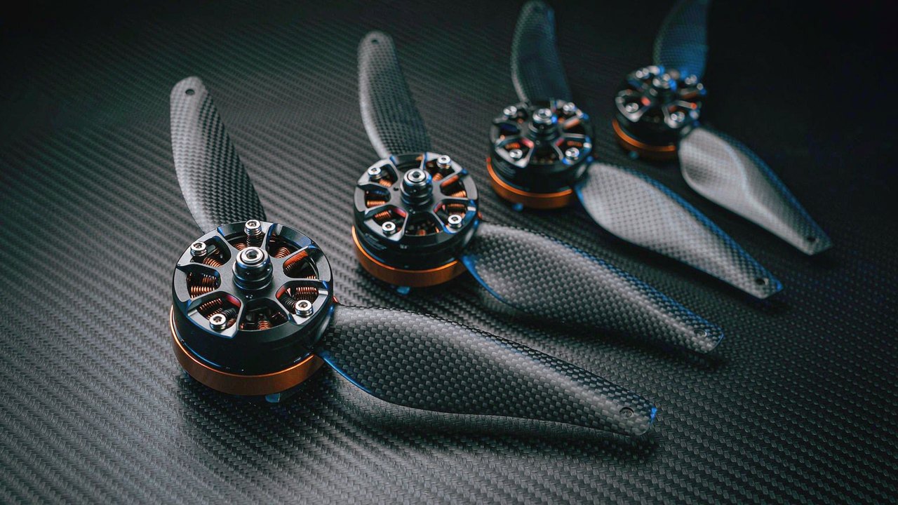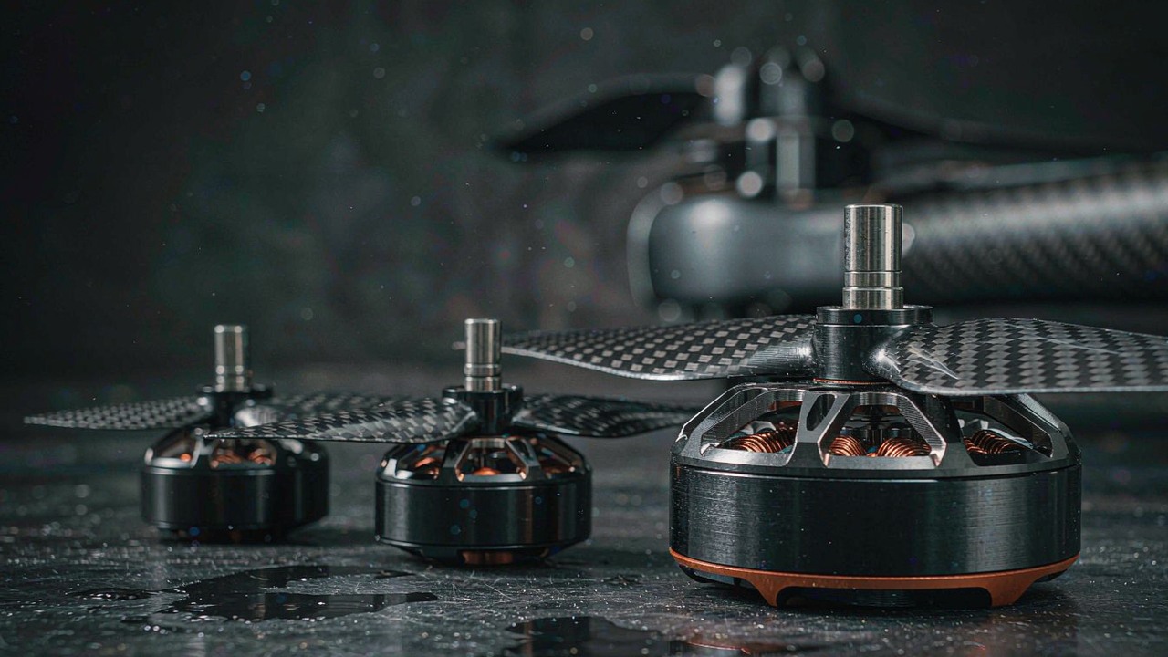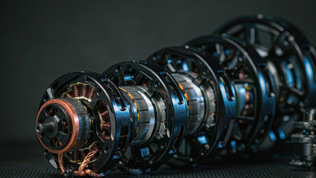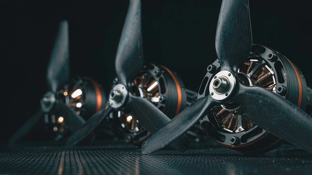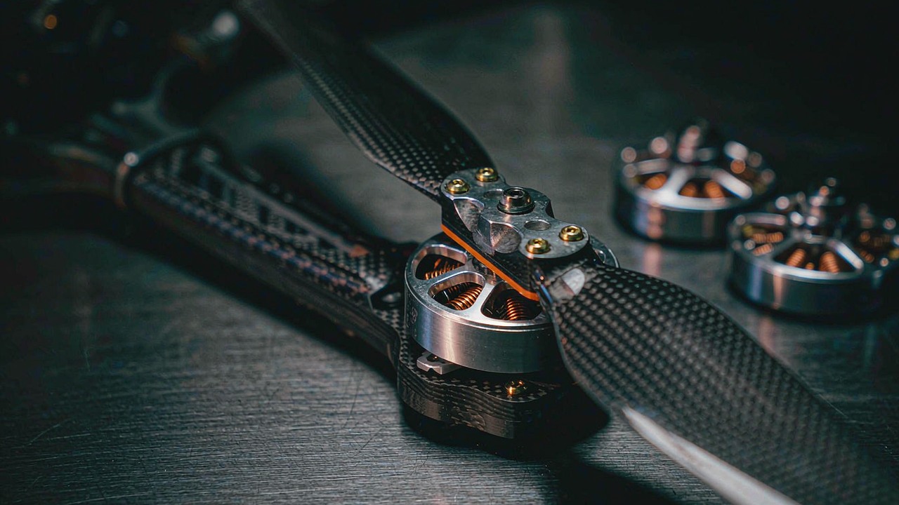
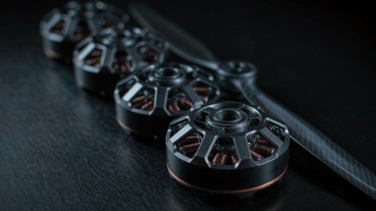
An aerial photography drone motor is picked for what it has to lift and for how steadily it holds that mass in the air, not for the largest thrust figure in a product range. A camera-lift airframe asks two questions at once: enough thrust per rotor to carry the camera, the gimbal and the pack, and a winding that stays smooth and cool while the aircraft holds a slow, part-throttle hover. The four T-Motor records compared here - the MN4006 KV380, the MN6007 II KV160, the MN7005 KV230 and the U7 KV280 - span 68 g to 317 g of published mass and 2309 g to 6419 g of published thrust, and that spread maps closely onto camera payload class. The same duty is described on the Aerial Photography UAV application page.
Quick Answer
Camera mass sets the brief before any motor number does. A camera-lift multirotor carries a gimbal whose own mass is a fraction of the airframe, and every gram spent on the camera and its stabilisation is a gram the propulsion group has to lift, hold and correct for. The practical consequence is that an aerial photography drone motor is chosen at the thrust it has to produce at the hover point rather than at the thrust it can produce for a moment at full throttle. The four records here are published at very different points along that scale: 2309 g, 4640 g, 4691 g and 6419 g, on propellers from 16 in to 24 in and on buses from 4-6S to 12S.
Two columns in this group carry more weight than their width suggests. The first is published thrust, because a camera-lift aircraft has to hold its thrust for minutes at a time rather than for the seconds a racing quad spends at full throttle. The second is internal resistance, because motor mass and winding resistance trade against each other inside a fixed stator size, and the resistance term is the one that turns hover current into copper loss in a housing without active cooling. Winding resistance is what makes copper loss estimable, but it is not the whole of motor heating: the temperature a motor reaches also depends on its other losses and on how the heat leaves the housing. Reading those two columns together separates a light record built for a small camera platform from a heavier record built to hold a large gimbal in a steady wind.
Where the four divide is at the bus rather than at the thrust. One record is published for 4-6S, one for 6S, one for 12S and one across 3-8S, and the KV figures follow that division, running from 160 KV on the 12S record to 380 KV on the 4-6S one. Because KV is shaft speed per applied volt, records at different cell counts reach comparable shaft speeds from different pack voltages, and the figure that separates them is the current each one draws for its published thrust. That is the chain an aerial photography drone motor is selected through, and the sections below take it apart in order.
What Counts as an Aerial Photography Drone Motor
An aerial photography drone motor is a propulsion component selected against a camera payload rather than against a performance target. That single change of reference moves the emphasis from peak numbers onto the part of the operating range the aircraft actually uses, because a camera platform climbs once, settles, and then holds altitude for most of its flight. The two sections below take the consequences of that shift in order: how much thrust each rotor has to hold, and how the winding is matched to it.
Thrust per Rotor Against Camera Mass
Thrust per rotor is a division before it is a specification. The all-up mass of the aircraft, divided by the number of rotors, gives the thrust one motor has to produce to hold the aircraft still, and that figure is a floor rather than a target. A camera-lift design normally leaves headroom above the hover point so that the flight controller can raise thrust on individual rotors to correct attitude, and that headroom is what separates the published thrust figure from the working point. The 2309 g record in this group and the 6419 g record are not two answers to the same question; they are answers to questions set by different camera masses and different rotor counts, and neither figure is useful until the airframe mass and the rotor count are fixed. An aerial photography drone motor is therefore sized from that division rather than from a peak figure in a product range.
KV as the First Filter for a Camera-Lift Airframe
KV is the first filter because it joins the two decisions that are hardest to change later: the propeller and the pack. A large, slow propeller with a low disk loading is what a camera platform wants, and a large propeller needs a lower shaft speed for the same thrust than a small one. KV is rpm per volt, so the shaft speed a record reaches is the product of its KV and the bus voltage attached to it. That is why the 12S record here carries the lowest KV in the group and the 4-6S record the highest, and why a KV figure quoted on its own says nothing about how fast a motor will turn in a particular airframe.
How Camera Mass Sets the Aerial Photography Drone Motor Brief
Camera mass reaches the motor through the payload budget, and the payload budget is what sets the rotor count and the thrust each rotor has to hold. An aerial photography drone motor therefore sits at the end of a chain that starts with the camera and its gimbal, and the two steps below are where that chain is longest.
How Payload Class Sets the Rotor Count
A small camera on a compact gimbal fits a light multirotor with a modest rotor count, and a large cinema camera on a stabilised mount needs either more rotors or larger ones. The two levers are not equivalent: adding rotors divides the thrust requirement and adds mass and drag at the same time, while enlarging the propellers raises the thrust available from each rotor without adding a motor. In this group the smallest record publishes 2309 g of thrust on a 16 in propeller and the largest publishes 6419 g on a 22 in propeller, so the payload class each one serves is set as much by the propeller it is published with as by the winding inside it. That is why an aerial photography drone motor is chosen against the payload class rather than against the airframe size.
Hover Throttle and Part-Throttle Headroom
Hover throttle is where a camera platform spends its battery, and it is a fraction of the published thrust band rather than a fixed percentage of it. The manufacturer test data makes the shape of that band visible. On the U7 KV280, the published test data for the 22 × 6.6 in CF propeller at 24 V reports 1565 g of thrust at 10.52 g/W at the 50% throttle point, against 4640 g at 5.51 g/W at full throttle. Under those stated test conditions the lower-throttle point delivers more thrust per watt, and the published full-throttle figure is a ceiling for the design rather than the point the mission runs at. The 50% point is not a universal hover target, though: the operating point an airframe settles at depends on its all-up mass, its rotor count, the propeller fitted and the thrust reserve the flight controller needs for attitude control.
Vibration and Hover Throttle in a Camera-Lift Airframe
Vibration reaches the image through the gimbal, and the gimbal is sensitive in exactly the band a multirotor produces at hover. The motor contributes to that band through two routes: the torque ripple it delivers to the propeller, and the way its own mass behaves on the mount. Both routes are set by design choices that the specification columns describe only in part, and both matter more on an Aerial Photography UAV than on an airframe flown for speed, because the image is the payload rather than a by-product of the flight.
Cogging, Pole Count and Low-Speed Smoothness
Cogging is the torque variation felt as the rotor passes from one stator tooth position to the next, and it depends on the slot-and-pole combination as well as on the magnetic design of the motor, its air gap and its manufacturing tolerances. The 18N24P and 24N28P configurations in this group put many steps into one revolution, and that is useful design context, but slot-and-pole counts alone do not establish which record produces less cogging torque or lower vibration at hover. Where a manufacturer publishes measured cogging torque, rotor balance or vibration data, those are the figures to compare, and the complete motor-propeller assembly is what has to be assessed under the intended operating conditions.
Motor Mass, Mount Stiffness and Damping
Motor mass, mount stiffness and damping interact to determine the vibration behaviour of the assembled propulsion system. Changing either the motor mass or the mount stiffness can shift structural resonances, but whether that improves image stability depends on the resulting modal frequencies, on the excitation sources and on how the gimbal responds, so the effect is assessed at the assembly level rather than inferred from motor mass alone. What the mass column does carry is a cost that is not in doubt: the record at 317 g and the record at 68 g in this group sit at opposite ends of the load the other rotors have to lift for the whole flight. Because the comparison carries no mount structure, vibration spectrum or modal result for the four records, the columns here support a mass reading rather than a ranking of which one absorbs disturbance better.
Aerial Photography Drone Motor: Spec Comparison Matrix
The four records compared here are the T-Motor models whose published duty is camera lift, set out as one specification set and ordered by published mass so that the step from the lightest record to the heaviest is visible in the column itself. Every value is the figure the manufacturer publishes for that model at the propeller named beside it, and no cell is estimated. Where a record does not carry a field, the table says so rather than filling the gap. All four are mounted in the same UAV Motors category and the same Aerial Photography UAV duty, and each is a candidate aerial photography drone motor for a different payload class.
| Model | Configuration | Internal Resistance | No. of Cells (LiPo) | Maximum Thrust | Test Propeller | Weight |
|---|---|---|---|---|---|---|
| MN4006 KV380 | 18N24P | 194 mΩ | 4-6S | 2309 g | 16 × 5.4 in CF | 68 g |
| MN6007 II KV160 | 24N28P | 178 mΩ | 12S | 6419 g | 22 × 6.6 in | 159 g |
| MN7005 KV230 | 24N28P | 71 mΩ | 6S | 4691 g | 24 × 7.2 in CF | 188 g |
| U7 KV280 | 12N14P | 71 mΩ | 3-8S | 4640 g | 22 × 6.6 in CF | 317 g |
Model, stator configuration, internal resistance, published cell count, maximum thrust, test propeller and weight as published by the manufacturer for the four camera-lift records compared here, ordered by published weight. Maximum thrust is the figure published for each model at the propeller named beside it, and it depends on that propeller and on the bus voltage used in the test, so the column is comparable within the group only in the sense that it describes each model's own published condition. The cell count is shown as published, so a single figure means a single published window and a range means that model is published across the range. Weight includes the cable and connector. No separate column repeats the KV figure because every model name in the table carries its own KV figure.
Two readings stand out once the four are on one page, and neither is the thrust column. The first is that internal resistance does not follow the same order as motor mass in this four-model set. The MN4006 KV380 and the MN6007 II KV160 list 194 mΩ and 178 mΩ respectively, at 68 g and 159 g of published mass, while the MN7005 KV230 and the U7 KV280 each list 71 mΩ. Those are useful specification differences, but resistance on its own does not establish a winding construction or predict which record runs cooler at hover: the copper loss a record produces depends on the current and the resistance definition that belong to its own operating point, and the total heating of a motor also depends on its other losses and on its cooling conditions.
The second reading concerns the two records that sit closest together in thrust. The MN7005 KV230 publishes 4691 g and the U7 KV280 publishes 4640 g, a difference of 51 g, yet the two are 129 g apart in mass and carry different stator configurations and different bus windows. Near-identical published thrust with a different stator layout and a different cell count is the clearest reminder in the table that thrust is a property of a motor together with a propeller and a voltage, and that mass and resistance are packaging outcomes rather than descriptions of duty. Choosing between them turns on the bus the airframe can carry and on the distance from the motors to the electronics, not on the 51 g.
A third reading is the bus. Two records are published for a single voltage, 6S and 12S, and two across a window, 4-6S and 3-8S. The single-voltage records are characterised at one working point, which makes them easy to compare but narrow to integrate, while the windowed records leave the pack choice open. For a camera-lift build the window matters because the pack is often selected after the airframe, and a record published across 3-8S or 4-6S keeps that decision available.
Matching an Aerial Photography Drone Motor to Bus Voltage and Propeller Class
An aerial photography drone motor is only defined once a bus voltage and a propeller are attached to it, because those two inputs turn a KV figure into a shaft speed and a thrust into a current. The two sections below take the inputs in the order they constrain each other.
Bus Voltage Window
The bus window published for an aerial photography drone motor is the range of pack voltages the manufacturer has characterised. For a given level of shaft power under comparable conditions a higher bus voltage generally allows a lower supply current, which lowers copper loss, and a higher cell count also means a heavier pack and a higher-rated ESC. The bus choice on its own is not enough to rank these four records by hover current or by propulsion efficiency, though, because their motor characteristics, propellers, thrust requirements and operating points all differ; pack mass, ESC compatibility and the manufacturer's test data for the intended working point are read together when the bus is selected. In this group the windows run from 4-6S on the MN4006 KV380 through 6S on the MN7005 KV230 and 3-8S on the U7 KV280 to 12S on the MN6007 II KV160, so the widest single window and the highest single voltage sit on different records and serve different airframes.
Propeller Class and Thrust per Rotor
The propeller sets the shaft speed the motor has to reach and the torque it has to deliver, and the published thrust figures are quoted at a named propeller for that reason. The 16 × 5.4 in CF on the MN4006 KV380, the 22 × 6.6 in on the MN6007 II KV160, the 24 × 7.2 in CF on the MN7005 KV230 and the 22 × 6.6 in CF on the U7 KV280 place the four records in different diameter classes, and the thrust each one publishes follows from its own propeller rather than from its stator alone. A record quoted at a large, slow propeller will not reproduce its published thrust on a small, fast one, and the figure to check before committing is the manufacturer's data for the propeller the airframe actually carries.
Camera-Lift Records Model by Model
Read as a group, the four records cover a camera-lift range that runs from a compact gimbal platform to a large stabilised mount, and between them they span the bus voltages an aerial photography drone motor is commonly published for. Each one is treated below with the fields its own record carries and nothing more.
MN4006 KV380
The MN4006 KV380 opens the group at 68 g including its cable, on an 18N24P stator with 194 mΩ of internal resistance and a 4-6S window. Its published 2309 g of thrust arrives on a 16 × 5.4 in CF propeller, and its record carries a 50 mm lead and an idle current of 0.3 A at 22 V. It is the record for the smallest camera-lift airframe in the set, where the camera and gimbal together are a fraction of a kilogram and the pack is small enough that the current per rotor stays modest at the 4-6S end of its window.
MN6007 II KV160
The MN6007 II KV160 is the 12S record in the group and the one with the highest published thrust, 6419 g on a 22 × 6.6 in propeller. Its 24N28P stator and 178 mΩ of resistance sit alongside a 159 g mass including cable, a 70 mm lead and an idle current of 0.5 A at 18 V. Low KV on a high bus is the arrangement a large, slow propeller wants, and its 12S rating, low KV and published thrust make it a candidate to evaluate for larger camera-lift configurations, provided the propeller, the hover operating point, the all-up mass and the electrical system are compatible with the intended airframe.
MN7005 KV230
The MN7005 KV230 carries the lowest internal resistance in the set at 71 mΩ, on a 24N28P stator and a 188 g mass including cable, and it publishes 4691 g of thrust on a 24 × 7.2 in CF propeller inside a 6S window. Its lead is 60 mm, its shaft measures 15 mm and its idle current is 0.9 A at 22 V. A 24 in propeller on a 6S bus is the widest disk in the group, and it is a combination built for holding a steady camera platform rather than for climbing hard.
U7 KV280
The U7 KV280 is the heaviest record here at 317 g including cable, and it carries the widest bus window in the group at 3-8S, which leaves the pack choice open for longer than a single-voltage record does. Its 12N14P stator carries 71 mΩ of resistance, its shaft measures 6 mm, its cable is 750 mm and its idle current is 0.5 A at 10 V, and the manufacturer publishes 4640 g of thrust on a 22 × 6.6 in CF propeller. The 750 mm lead and the 317 g mass are packaging and installation figures: the long lead suits a frame where the motors mount further from the electronics, and neither value states anything about the vibration the assembly produces.
Selecting an Aerial Photography Drone Motor: A Sizing Sequence
The three steps below apply the columns in the order that turns a camera payload into a shortlist.
Hover budget before motor numbers
The camera, gimbal, airframe and pack are weighed before any motor is read, because the all-up mass and the rotor count together give the thrust one rotor has to hold at hover. That figure then bounds the search: a record whose published thrust sits below the hover requirement at its own propeller cannot be rescued by a later step. Across this group the published thrust rises from 2309 g to 6419 g, and the two records in the middle sit within 51 g of each other despite a 129 g difference in mass, which is a reminder that the thrust column has to be read against the propeller and the bus rather than on its own.
Bus, propeller and winding together
The bus is a decision in its own right because it sets the pack mass and the ESC rating at the same time as it sets the hover current. A low KV on a high bus draws less current for a given shaft power under comparable conditions, which lowers copper loss, and it pays for that with a heavier pack. In this group the choice runs from the 4-6S record through 6S and 3-8S to the 12S record, and the resistance column marks the close calls: 194 mΩ and 178 mΩ on the two lighter records against 71 mΩ on the two records of similar published thrust. What that difference turns into depends on the current each record actually draws at its own operating point, so the column is read as an indication rather than as a temperature.
Mounting, mass and clearance last
Only after the duty, the bus and the winding have narrowed the list do the mounting details settle the choice, and by then the candidate set is short enough for shaft, lead and clearance to decide it. The mass column is read against the payload budget at this step rather than as a quality score. Where a record does not carry a field the build depends on, the honest move is to put the question to the manufacturer's documentation rather than to infer the value from a neighbouring model.
The three steps applied to this group give a shortlist rather than an answer:
- Compact camera platforms. The MN4006 KV380 is the 4-6S record at 68 g, and its published 2309 g of thrust on a 16 × 5.4 in propeller suits a light gimbal on a small frame.
- Mid-size stabilised camera airframes. The MN7005 KV230 and the U7 KV280 publish 4691 g and 4640 g on 24 × 7.2 in and 22 × 6.6 in propellers, and the choice between them follows from the bus the frame can carry and from how far the motors sit from the electronics.
- Large stabilised mounts on a high bus. The MN6007 II KV160 is the 12S record and publishes the highest thrust in the set at 6419 g on the lowest KV.
Frequently asked questions
QWhat KV does an aerial photography drone motor need?
There is no single figure that suits camera lift, because KV is rpm per volt rather than a quality of its own. A KV only becomes a shaft speed once a bus voltage is attached to it, and the shaft speed a camera platform wants follows from its propeller diameter. A large, slow propeller needs a low KV on a high bus, which is why the 12S record in this group carries the lowest KV at 160 and the smallest 4-6S record carries the highest at 380. The workable method for an aerial photography drone motor is to start from the propeller, establish the shaft speed it needs to produce the required thrust, and then choose the KV and cell count pair that reaches it.
QHow much thrust per rotor does a camera-lift drone need?
Thrust per rotor is the all-up mass divided by the rotor count, with headroom added for attitude control, and it is a requirement rather than a specification. A camera platform has to hold that thrust for minutes at a time while the flight controller raises and lowers individual rotors to keep the gimbal level, so the thrust an aerial photography drone motor is chosen against sits above the static hover requirement rather than at it. The published thrust figures in this group run from 2309 g to 6419 g, and each one is quoted at a named propeller, so the comparison only becomes meaningful once the airframe mass, the rotor count and the propeller diameter are fixed.
QIs a lower KV better for a heavier camera payload?
Not on its own. A lower KV is useful for a heavier camera payload only when it is paired with a larger propeller and a bus voltage that together place the motor at an efficient operating point. A low-KV motor on a small, fine propeller turns it too slowly to make useful thrust, while the same motor on a large, coarse propeller at the right bus turns it at the speed that propeller wants and draws less current for the same shaft power. In this group the KV figures run from 380 on a 4-6S record to 160 on a 12S record, and the two ends reach comparable shaft speeds from very different pack voltages. KV is a match to the propeller and the pack, not a quality of the winding.
QWhich T-Motor motors suit an aerial photography UAV?
The four records compared here cover the camera-lift range from a compact gimbal platform to a large stabilised mount. The MN4006 KV380 is the 4-6S record at 68 g and 2309 g of published thrust on a 16 × 5.4 in propeller; the MN6007 II KV160 is the 12S record and publishes the highest thrust in the set at 6419 g; the MN7005 KV230 publishes 4691 g on a 24 × 7.2 in propeller inside a 6S window; and the U7 KV280 publishes 4640 g on a 22 × 6.6 in propeller across a 3-8S window. The right one for a given airframe follows from the camera mass, the rotor count and the bus the frame can carry rather than from a ranking of the four.
QHow is vibration reduced in a camera drone motor?
Vibration is addressed at three points, and only one of them is inside the motor. Inside it, the slot-and-pole layout is design context for the cogging torque, but the slot-and-pole count alone does not settle how much cogging torque or vibration a record produces. At the interface, a balanced rotor and a mount matched to the motor are the factors that set the behaviour of the assembly, and where a manufacturer publishes a rotor dynamic balance standard it is one part of that picture. Above the interface, propeller balance and the mass of the whole propulsion group both act on the vibration that reaches the gimbal. A camera drone motor is therefore read for its low-speed torque behaviour as much as for its thrust, and measured cogging, balance and vibration data are the figures that answer the question.
Official resources
T-Motor publishes an official product page for each unit with its specification panel and test data, and those pages remain the source of truth for every figure quoted in this guide - for example the MN4006 KV380 product page, the U7 KV280 product page, the MN6007 II KV160 product page and the MN7005 KV230 product page. The resistance, cell count, thrust, propeller and mass figures in the table above are the values those pages publish for each model. A hover-current figure at a specific propeller and voltage, a thermal assumption behind a published power figure, or a field a record does not carry is a question for the manufacturer's documentation rather than a value that can be derived from the specification panel.
Where to go next
For shortlisting rather than reading, three tools on the platform do the work in sequence. Explore the full UAV Motors category to see these four camera-lift records alongside the heavy-lift, agricultural and VTOL models, use Select to narrow by cell count, mass and published thrust, then place candidates against each other in Compare Products. The Aerial Photography UAV application page holds the same duty with its own filter attributes.
Four further articles carry the parts of a camera-lift selection that a motor comparison does not settle. Gimbal Motors: Low-KV Direct Drive for Stable Camera Platforms covers the direct-drive axis that points the camera, which is a separate choice from the motors that lift it. BLDC Motors for Long Endurance UAV: Efficiency, Mass and Bus Voltage takes the same records and reads them against flight time rather than against payload, and How to Choose an Inspection UAV Motor: KV, Thrust and Stable Hover applies the same thrust and hover logic to a camera platform that has to hold position over one point. High Thrust Drone Motor Sizing: Payload, Efficiency, and Thermal Margin picks up the high-thrust end of the same subject, where the payload is large enough that thermal margin sets the motor.
The short version: weigh the camera and the gimbal first, because they set the all-up mass and the rotor count that an aerial photography drone motor has to serve; fix the propeller diameter second, because it sets the shaft speed the motor has to reach; match the KV to the bus third, because KV only becomes a shaft speed once a voltage is attached to it; and read the winding against the hover current last, because the published thrust figure sits above the point the mission runs at. Within this group that sequence separates the 68 g 4-6S record from the two mid-size records and from the 12S record before any individual model is weighed against another.