A BLDC motor and its electronic speed controller are specified in two different languages. The motor page talks in KV, thrust and peak current; the ESC page talks in continuous amps, cell count and commutation rate. Most propulsion problems that get blamed on firmware or tuning are decided at the moment those two briefs are compared — and the comparison only works when the motor side publishes enough to compare against. This guide sets out how motor ESC matching is done in practice: which three numbers cross the boundary, how pole count turns mechanical speed into an electrical one, where the current rating actually comes from, and why a documented motor makes the whole drone motor and ESC match checkable before the first flight.
Quick Answer
A drone motor and an ESC are matched on three figures: the KV rating, the current the motor will draw on the chosen propeller, and the cell count the pack will run. KV multiplied by pack voltage gives the no-load speed the controller has to commutate, and that speed multiplied by the pole pair count gives the electrical commutation rate it has to keep up with. The current figure decides the controller rating, and the cell count decides the voltage ceiling it must accept — at full charge, not at nominal.
The order matters. The propeller and the airframe set the thrust requirement, the thrust requirement sets the motor, and the motor plus pack sets the current and the electrical speed. The controller is selected last, from numbers the motor and propeller have already fixed. Working a drone motor and ESC match in the other direction — picking a controller first and finding a motor that survives it — almost always ends with either a controller running near its thermal limit or a motor held below the thrust it was bought for.
The practical difference between a straightforward match and a difficult one is usually documentation. A motor page that prints thrust at several throttle points, a peak current with the duration it holds for, the pole configuration and the wire gauge gives enough to size a controller on paper. A drone motor and ESC brief built on a page that prints only a KV and a mass cannot be closed the same way, and the gap has to be recovered on a test stand.
The Motor Is the Anchor, the ESC Is the Constraint
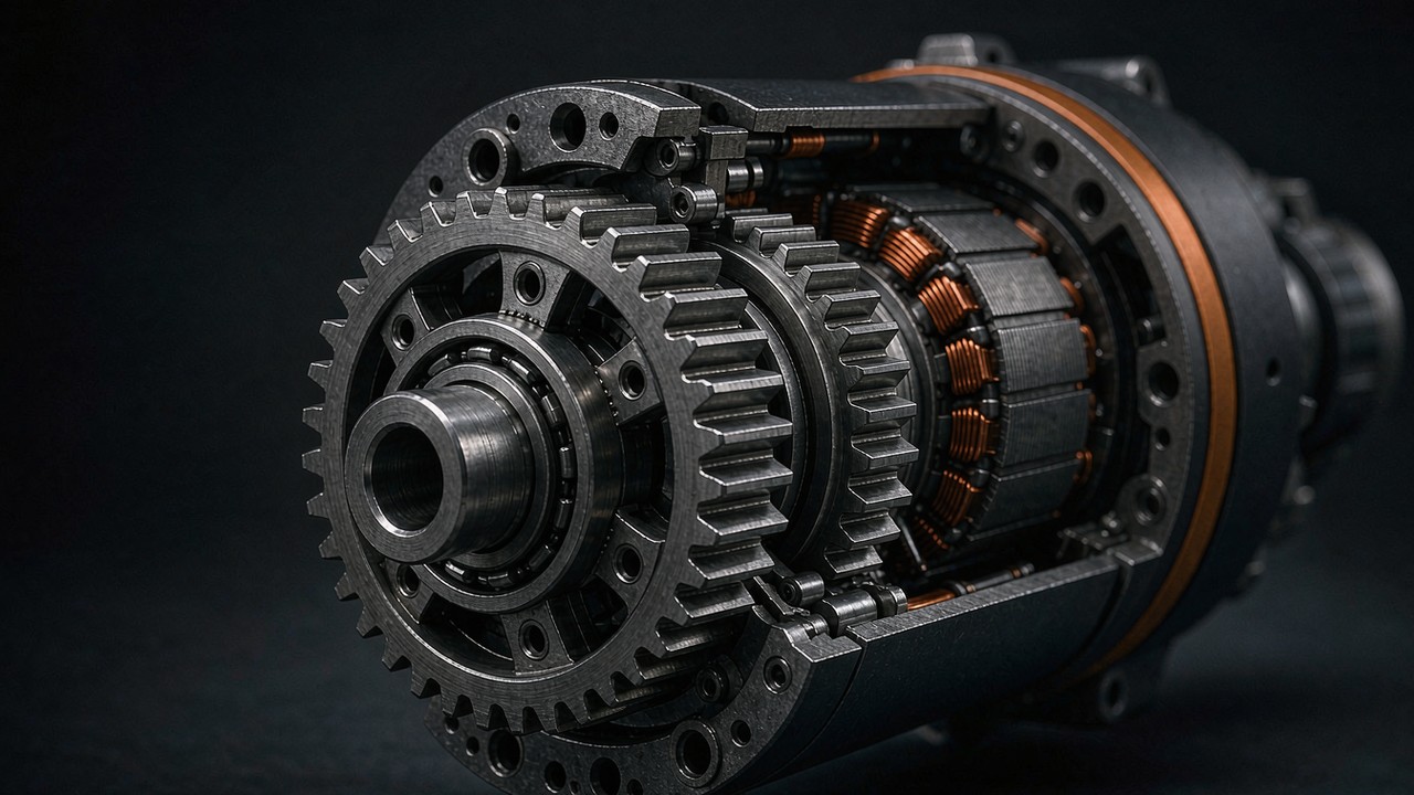
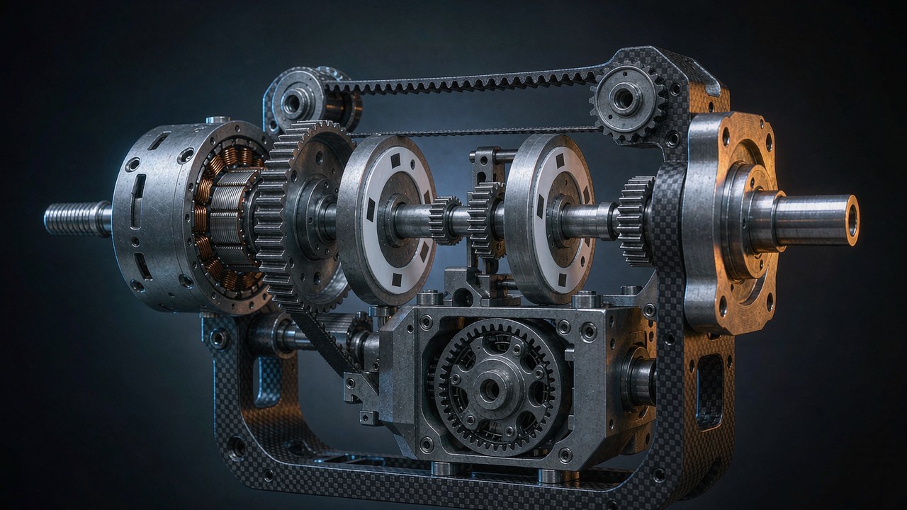
In a propulsion chain the motor converts electrical power into thrust, and the controller decides how quickly and how accurately that conversion can be steered. Treating the two as peers tends to produce a drone motor and ESC combination that is either over-built at the controller or under-built at the motor. Treating the motor as the anchor and the controller as a constraint keeps the sizing sequence in the right order, and that order is the basis of every motor ESC matching exercise that survives contact with a bench.
What the ESC does in the chain
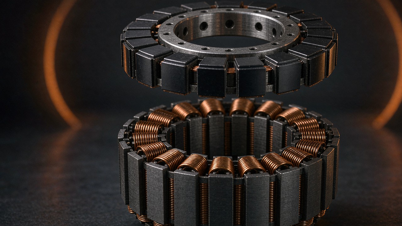
A brushless controller has no brushes to do the switching, so it synthesises the rotating field itself. It reads rotor position — from hall sensors, from back-EMF, or from both — and switches the three phases in the sequence that keeps the stator field ahead of the rotor. Every electrical revolution therefore contains a fixed number of commutation steps, and every mechanical revolution contains as many electrical revolutions as the rotor has pole pairs. That single relationship is why pole count, which looks like a motor detail, ends up as a constraint on the drone motor and ESC pair.
The controller also carries the whole phase current. On a 12S airframe running a large lift motor, that current can sit above 150 A for seconds at a time, and the switches, the shunt and the copper all have to survive it. The device is therefore both a timing element and a power element, and the two roles have separate limits: one is expressed in electrical RPM, the other in amps and degrees Celsius.
Why the motor brief comes first
Thrust is the requirement the airframe actually has. Hover thrust per rotor, climb margin and rotor count together fix a thrust target, and a thrust target at a given propeller diameter and cell count points at a narrow band of motor sizes. Once the motor is fixed, its published data fixes the current at the chosen propeller and the speed that has to be commutated. Working in this order means every downstream number in a drone motor and ESC specification has a source, which is the only way a match can be checked without a bench.
The three numbers that cross the boundary
Three quantities travel from the motor brief to the controller brief: KV, which converts pack voltage into speed; the current the propeller will draw, which sets the controller rating; and the pole count, which converts mechanical speed into electrical commutation rate. A fourth figure — internal resistance — does not size the controller directly, but it predicts how much of the pack voltage is lost as heat at high current, and therefore how much of the nominal voltage remains to make speed. That fourth figure is often what separates two drone motor and ESC combinations that look identical on paper.
Three Numbers That Tie a Drone Motor and ESC Together: KV, Peak Current and Cell Count
KV: speed per volt
KV is the no-load speed constant, expressed in revolutions per minute per volt. A motor marked KV160 turns at roughly 160 rpm for every volt applied, so on a 12S pack at 44.4 V nominal it reaches about 7104 rpm with no propeller fitted. The figure is a property of the winding — fewer turns of thicker wire raise KV, more turns of thinner wire lower it — and it says nothing directly about torque. Two motors with the same KV can differ substantially in mass, resistance and continuous torque, which is why KV alone is a poor basis for a drone motor and ESC selection.
For controller matching, KV does one job: it predicts the speed that has to be commutated at the top of the throttle range. A high-KV motor on a low cell count and a low-KV motor on a high cell count can arrive at the same mechanical speed from opposite directions, and the controller sees the same electrical rate either way.
Peak current: what the switches must carry
Current is set by load, not by the motor label. A motor rated at 57 A peak draws that current only when the propeller demands the torque that produces it — at full throttle, on a fresh pack, with the specified propeller. The same motor on a smaller propeller draws less and runs cooler; on a larger one it draws more and may exceed its own published window. This is the figure that most often decides a drone motor and ESC pairing in practice.
Published peak current therefore has to be read together with the propeller and cell count it was measured on, and with the time window it is valid for. A figure quoted over 180 s describes a different thermal situation from one quoted over 15 s, and a controller sized against the wrong window will be either oversized or unprotected.
Cell count: the voltage ceiling
The pack decides the voltage the controller must block and the speed the motor will attempt. A 12S pack is 44.4 V nominal but 50.4 V at full charge, and a 24S pack is 88.8 V nominal and 100.8 V at full charge. Controllers are rated against the voltage they will actually see, so the full-charge figure is the one that matters at the top of the throttle range. Margin between the pack’s full-charge voltage and the controller rating is what absorbs regenerative spikes when a large propeller is decelerated quickly — a detail that only appears in a drone motor and ESC match when the cell count is high.
What the Motor Side Has to Publish
Matching a drone motor and an ESC is an exercise in reading two sets of published data against each other. When one side is thin, the comparison degrades into guesswork, and guesswork at 150 A is expensive. Four fields do most of the work in motor ESC matching, and each of them is visible on a well-documented product page.
Thrust at more than one throttle point
A single headline thrust figure tells a design team what the motor can do at full throttle on one propeller. A thrust table that steps through 50 percent, 75 percent and 100 percent tells how much of that thrust is available at the throttle the aircraft actually cruises at, and what current each step costs. Hover is rarely at full throttle, so the part-throttle rows are the ones that decide flight time and controller heating — and they are the rows a drone motor and ESC match should be built on.
The duration behind a current figure
Peak current without a window is an incomplete number. A motor that holds 150 A for 15 s and one that holds 150 A for 180 s are different machines, and the difference is thermal mass in the windings and the stator. The window also tells the controller designer how long the burst rating has to last, which is a more useful input than the burst number alone.
Pole configuration and lead gauge
The pole configuration — written as a slot and pole count such as 12N14P or 36N42P — sets the electrical commutation rate and the smoothness of low-speed operation. The lead gauge sets the current the cable can carry without excessive heating, and therefore whether the controller rating can actually reach the motor. A controller rated at 200 A connected through a lead sized for 100 A is a 100 A system whatever the label says, which is one of the quietest ways a drone motor and ESC match can be derated.
Internal resistance and the voltage that reaches the motor
Internal resistance is the smallest field on the page and one of the most informative. At 150 A, a 40 mΩ winding drops 6 V — a meaningful fraction of a 44.4 V pack — and dissipates 900 W as heat inside the motor. Two motors with the same KV and the same thrust can have very different resistance, and the lower-resistance one will hold speed better under load and run cooler at the same current. For a drone motor and ESC match at the top of the current range, this single field often explains a difference the headline numbers do not.
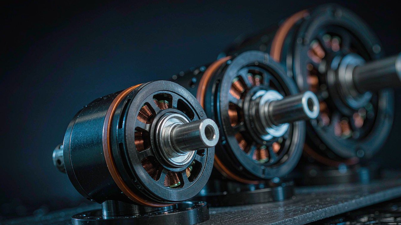
Eleven AT and V Records Read as One Specification Set
The records below are drawn from the manufacturer pages of eleven T-Motor models, split between the AT fixed-wing family and the V lift family. They are presented as one set because they show the same drone motor and ESC problem at three very different scales: a 60 g motor on 4S, a 350 g motor on 12S, and a 1680 g motor on 24S. For the fixed-wing end of the set, the airframe side of the choice is worked through in BLDC Motors for Fixed-Wing Model: Matching KV, Propeller and Cruise Power.
| Model | KV | LiPo | Max power (W) | Peak current (A) | Max thrust (g) |
|---|---|---|---|---|---|
| AT2312 KV1150 | 1150 | 2-4S | 350 | 25 (180 s) | 1244 |
| AT2317 KV880 | 880 | 2-4S | 350 | 25 (180 s) | 1670 |
| AT2321 KV950 | 950 | 2-4S | 450 | 30 (180 s) | 1912 |
| AT2820 KV880 | 880 | 3-4S | 700 | 45 (180 s) | 2755 |
| AT2826 KV900 | 900 | 3-4S | 820 | 57 (180 s) | 3409 |
| AT4125 KV250 | 250 | 12S | 2200 | 50 (180 s) | 7053 |
| V804 KV170 | 170 | 12S | 5200 | 115 (duration not published) | 17358 |
| V807 KV170 | 170 | 12S | 6800 | 150 (duration not published) | 20997 |
| V10 KV160 | 160 | 12S | 7000 | 155 (duration not published) | 27976 |
| V10L KV170 | 170 | 12S | 9000 | 196 (duration not published) | 31798 |
| V13L KV65 | 65 | 24S | 6000 | 190 (15 s) | 55454 |
Source: manufacturer product pages for each model. Thrust figures are the maximum stated for the model and depend on the propeller used in the manufacturer test. A figure in brackets after the current is the duration over which that peak is stated; where the page gives no duration, the bracket reads duration not published. For V13L, the published power figure and the published current at the nominal 24S voltage do not reconcile, so the row is used here for thrust and current only, pending clarification of the test condition from the manufacturer; the published power figure for that row is not used in any thrust-to-power comparison.
The AT fixed-wing rows
The AT rows span 60 g to 350 g and 2S to 12S. AT2312 through AT2321 sit in the same 350-450 W band on 2-4S, and the thrust progression from 1244 g to 1912 g comes largely from the longer stator rather than from KV, which moves in both directions across the three: 1150, 880 and 950 rpm/V. AT2820 and AT2826 take the same 12N14P layout up to 700 W and 820 W on 3-4S. AT4125 jumps to 12S and 2200 W, and its KV drops to 250 rpm/V — the winding is much slower because the pack voltage is much higher.
The V lift rows
The V rows are the lift side of the same problem. V804 and V807 share KV170 and 12S but differ in stator volume, which shows up as 5200 W against 6800 W and 17358 g against 20997 g of thrust. V10 and V10L share a 36N42P layout and 12S, and the larger V10L trades KV170 for KV160 while moving from 7000 W to 9000 W. V13L is the outlier: 42N38P, KV65, 24S, and 55454 g of thrust from a 1680 g motor. Read as a set, these rows show how far a drone motor and ESC brief can move on stator volume alone.
A cross-check that takes ten seconds
Peak current multiplied by nominal pack voltage should land close to the published maximum power. For V10, 155 A at 44.4 V gives about 6882 W against a published 7000 W. For V10L, 196 A at 44.4 V gives about 8702 W against 9000 W. For AT2826, 57 A at 14.8 V gives about 843 W against 820 W. The agreement is not exact — the figures come from different points on the test curve — but a row where the product is far from the power figure is a row to query before it is used to size a controller in a motor ESC matching decision.
Pole Count Turns RPM Into Commutation Rate
Pole pairs, not poles
The electrical rate depends on pole pairs. A 12N14P motor has 14 magnets, which is 7 pole pairs, so one mechanical revolution contains seven electrical revolutions. A 36N42P motor has 21 pole pairs, and a 42N38P motor has 19. For the same mechanical speed, these three configurations present the controller with electrical rates in a ratio of 7 to 21 to 19. Nothing else in a drone motor and ESC brief is as easy to overlook as this ratio, and the lift-side version of the calculation is set out in VTOL Drone Motors: Balancing Hover Thrust and Cruise Efficiency.
A worked example at 24S
V13L is marked KV65 on 24S. At 88.8 V nominal, KV multiplied by voltage gives about 5772 rpm at the shaft with no propeller fitted. With 19 pole pairs, that is roughly 109668 electrical revolutions per minute. The same arithmetic on V10 at KV160 and 12S gives about 7104 mechanical rpm, which at 21 pole pairs is roughly 149184 electrical rpm — a higher electrical rate from a slower-looking combination, purely because of the pole count.
What the controller has to do with the number
Electrical RPM is the rate at which the controller must resolve rotor position and switch phases. It is the number to compare against a controller’s stated commutation limit, and it is the number that explains why a high-pole-count lift motor can be harder to drive than a low-KV motor of similar power. The figures above are no-load estimates from published constants, so they are upper bounds: under propeller load the shaft slows and the electrical rate falls with it. Estimating at the top of the range is still the right habit, because the moment of least load — a throttle punch on a fresh pack — is exactly when a drone motor and ESC pair is most likely to lose sync.
Current Headroom: Where the ESC Rating Comes From
An ESC for a drone motor is rated in pairs: a continuous figure that can be held indefinitely and a burst figure valid for a stated number of seconds. The motor publishes a similar pair, although often only as a peak with a window. A workable rule is that the continuous rating should cover the current the propeller draws in the mission’s dominant condition — hover for a multirotor, cruise for a fixed wing — and the burst rating should cover the motor peak over at least the same window the motor claims. The thrust-to-margin arithmetic behind that rule is set out in High Thrust Drone Motor Sizing: Payload, Efficiency, and Thermal Margin.
Sizing on the motor peak alone is a common error in the other direction: a controller bought to match a 196 A peak may be twice the mass and cost needed for a machine that draws 60 A in hover and touches peak for two seconds on a climb. The drone motor and ESC match is therefore a match to the mission, not to the maximum of each field.
The gap between bench and airframe
Manufacturer thrust and current figures are measured on a bench with a stated propeller, a stable supply and free airflow. In an airframe the same motor sees a warmer intake, a less ideal supply and a propeller unloading differently in forward flight. The current at a given throttle can therefore differ from the table in either direction, which is why a first flight at reduced throttle with logged current is worth more than a careful paper match alone.
Voltage Bands and the Cell Count the ESC Must Accept
Nominal versus full charge
A 12S pack is called 44.4 V and reads 50.4 V when full; a 24S pack is called 88.8 V and reads 100.8 V. Controllers are rated at the voltage they must withstand, and the withstand case is the full pack plus whatever the propeller pushes back during deceleration. A controller rated at 50 V on a 12S pack has no margin at full charge; one rated at 60 V has, and the margin is the cheapest insurance in the chain.
The bands in the records
The eleven records fall into three bands. The AT2312 to AT2321 group runs 2-4S, which puts a 4S pack at 16.8 V full charge and keeps controller selection in the small, inexpensive class. AT2820 and AT2826 add a cell and stay in the same class. AT4125 and the four V lift motors run 12S, which is where controller choice starts to matter for voltage margin and where 100 A-class continuous ratings become normal. V13L runs 24S and sits alone at the top of the range, with the highest cell count and the lowest KV in the set — the combination that puts the widest spread between nominal and full-charge voltage into a single drone motor and ESC decision. The voltage side of the broader trade is worked through in BLDC Motors for Long Endurance UAV: Efficiency, Mass and Bus Voltage.
Where the pack voltage is fixed by an existing airframe rather than by choice, the lift-side comparison of complete propulsion sets is a faster route than a single-motor search: T-Motor VL Series: 16 VTOL Propulsion Sets from 12 kg to 150 kg MTOW.
Propeller Load Decides the Current, Not the Label
Same KV, different propeller
Two motors with the same KV and the same cell count can draw very different current from the same pack, because current follows the torque the propeller demands. A larger diameter or higher pitch loads the motor harder at every throttle setting, and the current rises faster than the thrust does. This is why a motor that looks comfortable on a 10 in propeller can be outside its window on a 12 in one, and why the propeller belongs inside the motor ESC matching brief rather than after it.
Reading thrust per amp
Dividing published thrust by published current at the same test point gives a rough efficiency index for comparing candidates, and it is the number that decides flight time. AT2312 returns about 50 g per amp at its peak point; AT4125 returns about 141 g per amp. The comparison is not like for like — the two are measured on different propellers at different points on the curve — but within one family and one test condition, the index separates efficient combinations from merely powerful ones.
A Matching Sequence From Prop to ESC
Five steps, in this order, keep every number in a drone motor and ESC match traceable to a source.
Step one: fix the thrust target. Hover thrust per rotor comes from all-up mass, rotor count and the thrust-to-weight margin the mission needs. Climb and wind margin are added here, not later.
Step two: choose the propeller and cell count. These two together set the operating point. A larger propeller at a lower KV and a smaller propeller at a higher KV can reach the same thrust, and the choice trades disc loading against motor mass.
Step three: pick the motor from thrust at the cruise throttle. The relevant row is the one at the throttle the aircraft holds in the mission, not the full-throttle headline. Read the current at that row as well, because it is the current the controller will carry for most of the flight.
Step four: convert the motor into a controller brief. Multiply KV by the pack’s full-charge voltage for the speed ceiling, multiply by pole pairs for the electrical rate, and take the peak current with its window. Those four figures are the whole brief.
Step five: select an ESC for a drone motor with margin on all three axes. Continuous current above the mission current, burst current above the motor peak over at least the stated window, and a voltage rating above the full-charge pack voltage. Confirm that the lead gauge and connector match the current the controller can deliver, because a mismatch there silently derates the chain.
Where a Drone Motor and ESC Mismatch Shows Up First
Desync at high electrical speed
The first symptom of a commutation limit being approached is usually a loss of sync under a rapid throttle change: the motor stutters, the controller shuts down, and the machine drops a corner. It happens at the moment of least load and highest rate, which is exactly the condition an electrical-rate estimate is meant to predict. A controller with more timing headroom, or a motor with fewer pole pairs for the same thrust, both move the margin in the right direction.
Heat in the switches
An ESC for a drone motor running near its continuous rating gets hot before it fails, and the heat is concentrated in the switches and the shunt. Sustained hover at 80 percent of a continuous rating in still air is a different proposition from the same current in a 25 km/h airflow. Thermal margin is part of the drone motor and ESC match, not a refinement of it.
Throttle resolution and voltage sag
A controller oversized for the motor spends the bottom of its range doing very little, and a pack near its current limit sags under load, which lowers the voltage the motor sees and therefore the speed it makes. Both effects show up as a machine that feels unresponsive at the point where response matters most — during a recovery or a gust. Neither is solved by changing the controller alone.
Why a Documented Motor Makes Motor ESC Matching Verifiable
Every step in the sequence above depends on a published number. Where the motor page prints thrust at multiple throttle points, a peak current with its window, a pole configuration and a lead gauge, the controller brief falls out of arithmetic and can be checked by a second engineer without touching hardware. Where those fields are missing, the same decisions have to be recovered from a test stand, and a test stand at 150 A is not a cheap substitute for a specification.
That is the practical argument for buying from manufacturers who publish complete propulsion data rather than a headline KV and a mass. A published thrust table is a commitment: it names the propeller, the cell count and the throttle points, and it can be re-measured. A published peak current with a stated window is a thermal claim that can be compared across models. A pole count makes the electrical rate calculable before the controller is chosen, and a lead gauge makes the current path checkable end to end. None of these fields is exotic, and all of them are visible on the records used in this article — which is what turns motor ESC matching from an opinion into an audit.
The same logic applies to the controller side: a controller whose continuous and burst ratings are stated with their test conditions can be matched to a motor in the same way. When both sides publish, the drone motor and ESC pairing stops being a matter of opinion and becomes a calculation that either closes or does not.
Key Takeaways
- The propeller sets the thrust, the thrust sets the motor, and the motor plus pack sets the controller brief — in that order, and that order is the whole of motor ESC matching.
- KV multiplied by full-charge pack voltage gives the speed ceiling; multiplied by pole pairs it gives the electrical commutation rate that a controller limit is measured against.
- Peak current is only meaningful with its duration and its test propeller. A 15 s figure and a 180 s figure describe different thermal realities.
- Controller voltage rating should be compared against the full-charge pack voltage, not the nominal one.
- Lead gauge and connector rating belong inside the current budget; a 200 A controller behind a 100 A lead is a 100 A system.
- Lower internal resistance holds speed better under load and runs cooler at the same current, which matters most at the top of the range.
- A documented drone motor and ESC match can be checked on paper before the first flight; an undocumented one has to be recovered on a bench.
Frequently asked questions
QWhat current rating does an ESC for a drone motor need?
Enough for the mission’s dominant condition on the continuous rating, and for the motor peak on the burst rating over at least the window the motor claims. The current the propeller draws in hover or cruise sits well below the continuous figure, while the peak appears only on climbs and fresh packs. Sizing purely on the motor peak tends to produce a controller that is heavier and more expensive than the mission requires.
QHow does pole count change the commutation rate an ESC must track?
One mechanical revolution contains as many electrical revolutions as the rotor has pole pairs, so the electrical rate is shaft speed multiplied by pole pairs. A 42-pole rotor at the same shaft speed presents three times the commutation rate of a 14-pole rotor. Controllers have a finite rate at which they can resolve position and switch phases, which is why a high pole count reduces the timing margin even when current and voltage look comfortable.
QWhy does a mismatch show up as heat before it shows up as thrust loss?
Because resistive and switching losses rise with current before the propeller stops producing thrust. A controller at 80 percent of its continuous rating in still air runs hotter than the same current in a 25 km/h airflow, and the heat concentrates in the switches and the shunt. Thrust only collapses once the controller derates or loses sync, by which point the thermal margin has already been spent.
QWhat happens when the ESC voltage band is narrower than the motor cell count?
The controller sees more than its rating at full charge, before any throttle is applied. A 12S pack reaches 50.4 V and a 24S pack reaches 100.8 V, so a controller rated below those figures has no withstand margin at the start of a flight or during deceleration of a large propeller. The rating should clear the full-charge voltage, not the nominal one.
QIs a higher current rating a safer match for a given propeller load?
Not automatically. A larger controller adds mass and cost, and it does not fix a commutation limit or a voltage margin problem. What it does buy is thermal headroom at the mission current, which matters where airflow over the controller is poor. The rating should follow the published current at the chosen propeller and cell count, plus the electrical rate at the resulting speed.
QWhat does a published thrust table add to a motor and ESC match?
It makes the match checkable rather than assumed. A table that names the propeller, the cell count and the throttle points allows the current at the mission throttle to be read directly, and the peak to be checked against its window. Without it, the same numbers have to be recovered on a test stand, which is why documented records shorten the path from a motor choice to a controller choice.
Official resources
The manufacturer pages behind each record carry the full test conditions, including the propeller and cell count used for the thrust and current figures. For the AT series and the V series, those pages are the primary source for every number in the comparison table, and they should be consulted before a final controller choice is fixed.
Explore Drone Motors for Fixed-Wing and VTOL Airframes
Individual records cited above are listed under Drone Motors, alongside the airframe categories they serve, including Fixed Wing Model. Where a motor page and a controller page disagree on the same current, the propeller and cell count behind each figure are the first thing to compare.