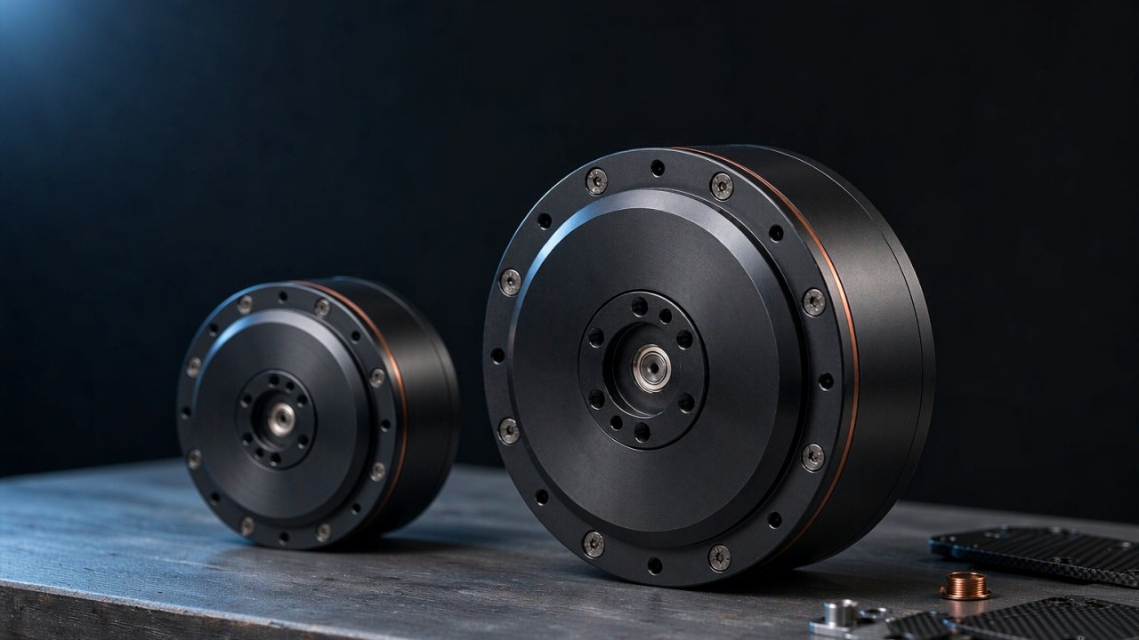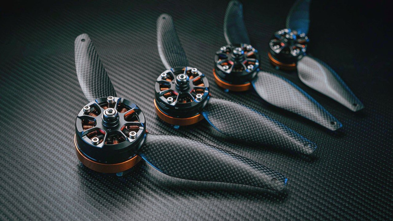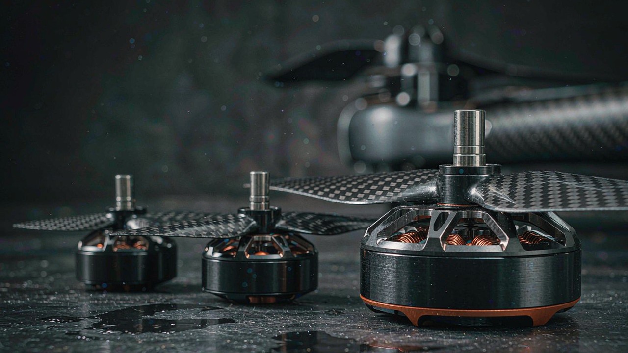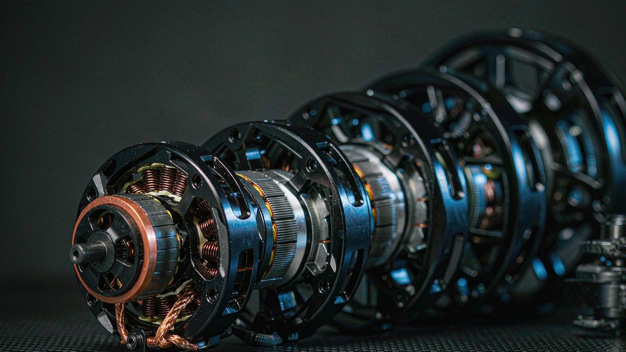
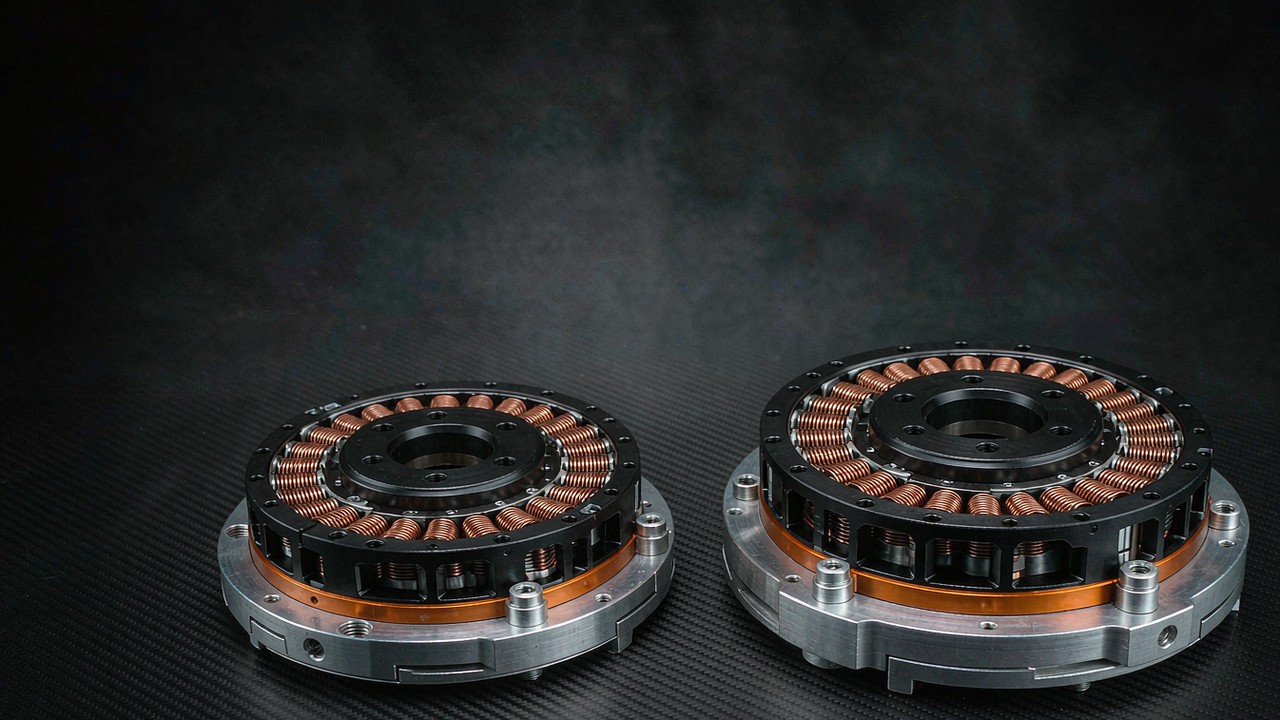
The AKE series from CubeMars now reaches down to 140 g. Two new modules, the AKE40-6 KV90 and the AKE50-8 KV110, sit below the 260 g AKE60-8 that previously anchored the small end of the family. Both are compact QDD actuators built around a low-ratio planetary stage, both run on a 24 V bus, and both leave the housing and the driver board off the module so the frame can be designed around them. This guide compares the pair on the figures a wearable joint is usually screened against — mass, torque, reduction ratio, back-drive torque and backlash — and keeps the manufacturer’s published applications separate from the system-level checks that still have to be made.
Quick Answer
The AKE40-6 KV90 is the lighter of the two at 140 g, with a 6:1 planetary stage, 1.8 Nm rated torque and 5.5 Nm peak torque at 260 rpm rated and 330 rpm no-load. The AKE50-8 KV110 weighs 190 g and uses an 8:1 stage, delivering 2.5 Nm rated and 7.5 Nm peak at 240 rpm rated and 320 rpm no-load. Both hold backlash to 0.15° and both are quoted at 24 V.
The split is deliberate, and it is visible in the published figures rather than inferred from the ratio alone. The 6:1 module is quoted at 5.5 Nm peak with 0.05 Nm of back-drive torque; the 8:1 module at 7.5 Nm peak with 0.09 Nm. A lower ratio generally reduces reflected inertia, but the two numbers also reflect different motors and transmission details, so the difference cannot be assigned to the ratio by itself.
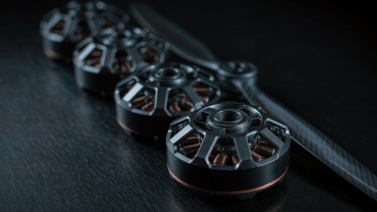
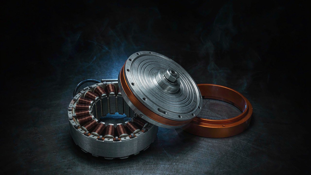
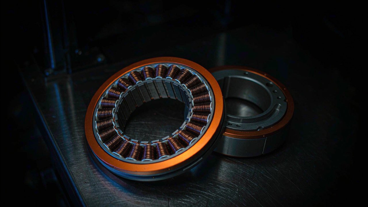
Neither compact QDD actuator carries an enclosure or an integrated driver board. That is a design choice rather than a gap: an exoskeleton frame is shaped around a limb, and a module that bolts to a custom bracket gains more from a bare motor base than from a universal shell.
Why Two 200 g Class Actuators Extend the AKE Series
What the series covered before
Until these two modules arrived, the AKE family started at 260 g. The AKE60-8 KV80 covered the light end with 5 Nm rated and 12.5 Nm peak, the AKE80-8 KV30 moved to 570 g and 12 Nm rated on a 48 V bus, and the AKE90-8 KV35 topped the range at 1400 g with 55 Nm rated and 170 Nm peak. Below 260 g the family had nothing, so the smallest Exoskeleton joints — fingers, wrists, ankles, foot-drop orthoses — were usually served by frameless kits or by belt and cable transmissions, because every AKE option was larger than the joint it needed to drive.
What the two new modules change
A 140 g compact QDD actuator changes the arithmetic at the end of a limb, provided the rest of the assembly is counted with it. Mass placed at a wrist or an ankle is accelerated through every step, and the further it sits from the torso the more it costs to carry. But 140 g is the module, not the assembled joint: brackets, fasteners, cabling and drive electronics all add to that figure. A motor mounted remotely and driving the joint through a Bowden cable is a different architecture with its own mass, friction and control consequences, and module mass alone does not settle which arrangement is lighter or easier to wear. What the smaller module does offer is an axial length of 24.5 mm, which may help packaging where the joint has to stay compact.
The 190 g compact QDD actuator does the same job one size up. At 22.5 mm it is thinner along the axis than its smaller sibling despite the larger diameter, which may suit a brace that has to sit close to the limb. Whether that is worth the extra 50 g depends on the frame, the mounting orientation and the space needed for connectors and cable routing.
Why a 6:1 and an 8:1 module arrive together
Two ratios cover two different torque and speed requirements rather than two fixed joint categories. A 6:1 stage leaves more output speed in place and generally reduces reflected inertia, which is useful where a joint moves through a wide arc with little load. An 8:1 stage trades some of that speed for torque multiplication, which fits a joint that needs more output at a lower speed. Which of the two a given joint should use is settled by its torque-speed profile and duty cycle; the ratio is one input to that decision, not the answer.
AKE40-6 KV90 and AKE50-8 KV110: Specifications Side by Side
The table below places both new compact QDD actuators against the three existing AKE sizes. Values are the manufacturer’s published figures for each model; where a figure is missing it is left out rather than estimated.
| Specification | AKE40-6 KV90 | AKE50-8 KV110 | AKE60-8 KV80 | AKE80-8 KV30 | AKE90-8 KV35 | Unit |
|---|---|---|---|---|---|---|
| Rated voltage | 24 | 24 | 24 | 48 | 48 | V |
| Rated power | 50 | 65 | 95 | 188 | 700 | W |
| Rated torque | 1.8 | 2.5 | 5 | 12 | 55 | Nm |
| Peak torque | 5.5 | 7.5 | 12.5 | 30 | 170 | Nm |
| Rated current | 2.5 | 3 | 4.8 | 4.8 | 21 | A |
| Peak current | 8 | 9 | 12 | 12 | 72 | A |
| Rated speed | 260 | 240 | 180 | 150 | 120 | rpm |
| No-load speed | 330 | 320 | 240 | 195 | 210 | rpm |
| Reduction ratio | 6:1 | 8:1 | 8:1 | 8:1 | 8:1 | — |
| Backlash | 0.15 | 0.15 | 0.15 | 0.15 | 0.15 | ° |
| Mass | 140 | 190 | 260 | 570 | 1400 | g |
| Outer diameter | 51 | 61.2 | 69 | 87 | 107.5 | mm |
| Axial length | 24.5 | 22.5 | 25 | 32 | 43.5 | mm |
| Pole pairs | 14 | 14 | 14 | 21 | 21 | — |
Published figures from the manufacturer’s product pages for each AKE model. Backlash is quoted in degrees; the AKE series is published as 9 arcmin, which equals 0.15°. KV is carried in the model name rather than repeated as a column. Torque values are at the joint side of the reducer, not the motor shaft.
One caution applies to the torque rows. Rated torque should be interpreted under the manufacturer’s specified operating and thermal conditions, not as a value that can be drawn continuously in any installation. Joint selection also has to account for the required torque-speed profile, duty cycle, mounting and cooling conditions, and transient loads; peak torque should not be treated as a continuous operating rating.
Read the first two columns together and the pair looks close: 50 g of mass, 0.7 Nm of rated torque and a single step of reduction ratio separate them. The voltage row separates the family instead — the two new modules and the AKE60-8 run at 24 V, while the AKE80-8 and AKE90-8 are published on 48 V. On a battery-powered wearable that row changes the supply architecture. A device that mixes the two needs a compatible arrangement, whether that is separate packs, a DC-DC converter or another design, and the choice belongs to the system rather than to the module.
The current rows are inputs to driver selection rather than a selection rule. A 2.5 A rated draw on the AKE40-6 and 3 A on the AKE50-8 describe continuous current; 8 A and 9 A describe peak current. The driver must support the specified continuous current and the required peak current for the relevant duration, with thermal derating, voltage compatibility and protection that fit the installation. The published figures do not by themselves determine the driver size, and they do not describe how the joint behaves under a disturbance. What can be said is narrower: a compact QDD actuator drawing 3 A continuously is a modest load for a pack that also runs sensors and a controller, which is a statement about current draw rather than about electronics sizing.
Mass and outer diameter move in opposite directions between the two: the AKE50-8 is 50 g heavier and 10.2 mm wider, yet 2 mm thinner along the axis. A joint that has to stay tight against a limb may favour the thinner module; one with radial clearance may accept the wider.
The AKE Range in One View: 140 g to 1.4 kg
The five modules form a ladder in mass and output torque rather than five interchangeable products. At the bottom, the CubeMars AKE40-6 KV90 Quasi Direct Drive Actuator is published at 1.8 Nm rated and 5.5 Nm peak, the smallest output in the family. The CubeMars AKE50-8 KV110 Quasi Direct Drive Actuator raises that to 2.5 Nm rated and 7.5 Nm peak at 190 g. Above them the CubeMars AKE60-8 KV80 Quasi Direct Drive Actuator at 260 g is published at 5 Nm rated and 12.5 Nm peak, the CubeMars AKE80-8 KV30 Quasi Direct Drive Actuator at 570 g at 12 Nm rated and 30 Nm peak, and the CubeMars AKE90-8 KV35 Quasi Direct Drive Actuator at 1400 g at 55 Nm rated and 170 Nm peak. CubeMars also publishes a set of applications for each model, from finger and wrist drives at the small end to hip assistance at the top; those are the manufacturer’s stated directions, and the joint section below keeps them separate from any inference drawn from the specifications.
The gap the two compact QDD actuators close is 120 g wide. The band from the AKE60-8 upward was already covered by a selection guide that starts at 260 g and runs to 1.4 kg; below that line there was no AKE module at all. A compact QDD actuator in the 140 g to 190 g band adds the same architecture at the bottom of the range — a low-ratio planetary stage, a bare motor base and no enclosure.
Torque density separates the ends of the ladder more than mass does. The AKE90-8 is published at up to 121 Nm/kg, which follows from a 170 Nm peak in a 1400 g package. At the small end the ratio of peak torque to mass is lower — about 39 Nm/kg for both new modules, 39.3 Nm/kg for the AKE40-6 and 39.5 Nm/kg for the AKE50-8 — so the absolute torque is modest and so is the mass that has to be accelerated with it. Why the ratio sits lower at that end is a question about winding, bearings and gear stage design, and the published table does not answer it; naming a single cause would go beyond the data. What the figures do support is the trade a compact QDD actuator makes at the bottom of a range: less torque to deliver, and less mass carried to deliver it.
140 g vs 190 g: Where the Mass Goes on a Compact QDD Actuator
Fifty grams sounds like a rounding error next to a 570 g module, and on a bench it is. At the end of a limb it matters more, because mass there is carried through every swing and the penalty scales with distance from the torso. Two caveats keep the number in proportion: 140 g and 190 g are module masses, not assembled joint masses, and brackets, fasteners, cabling and electronics add to both. The useful comparison is between two complete assemblies, not between two datasheet masses.
The axial dimension matters as much as the mass. A 24.5 mm module leaves more room inside a garment than a stack of motor, gearbox and coupling, and the AKE50-8 at 22.5 mm is shorter still. That can help a brace stay flat over the joint, but the final profile is set by the bracket, the mounting orientation, the connectors and the space left for cabling, so axial length is a starting advantage rather than a finished envelope.
Choosing between the two usually starts from the torque the joint needs at the wearer’s movement speed. A 6:1 compact QDD actuator at 1.8 Nm rated is the lower-torque option, which makes it worth evaluating where low module mass and a small torque requirement are the priorities; the 8:1 module at 2.5 Nm rated is the option where more output torque is needed inside a similar compact envelope. Where the requirement falls between the two, mass usually decides, and the 140 g module has the advantage — provided the assembled joint still meets its torque-speed and duty-cycle requirements.
6:1 vs 8:1: Speed, Torque and Back-Drive at 0.05 Nm and 0.09 Nm
The two compact QDD actuators differ in reduction ratio, rated output and published back-drive torque. A lower reduction ratio can generally reduce reflected motor inertia, but actual back-driving behaviour also depends on motor characteristics, transmission friction and efficiency. The published 0.05 Nm and 0.09 Nm figures describe these specific models; they should not be attributed to the reduction ratio alone. What the ratio does set directly is speed and torque at the output: the 6:1 stage on the AKE40-6 turns no-load motor speed into 330 rpm at the joint, and the 8:1 stage on the AKE50-8 gives 320 rpm at the joint in exchange for 7.5 Nm of peak torque.
Back-drive torque is the figure most often used to separate a compact QDD actuator from a geared servo, and the comparison is fair in direction rather than in absolute terms. A ratio in the tens or hundreds reflects the motor and the gearbox back to the output, and a wearer moving the joint has to work against that reflected load; a low-ratio stage keeps the reflected load smaller. How much resistance a specific high-ratio servo shows still depends on its motor, its transmission and its control state, so the published figures here are best read as a comparison between these two modules rather than as a general ranking of architectures.
The trade lands differently at each joint, and the published applications point in different directions. A wrist or a finger moves through a wide arc with little load, which is where the extra output speed of the 6:1 module is most usable; a knee or an elbow works through a narrower arc against a larger load, which is where the 8:1 module’s extra torque is relevant. Those are starting points drawn from the published figures and applications, not a demonstration that either module meets a particular joint’s load case. The mechanics behind reflected inertia and what a ratio does to the load a wearer feels are covered in Quasi Direct Drive Actuators: What an 8:1 Ratio Buys You.
The published back-drive torque figures provide a useful starting point for comparing the two modules, but they do not establish how an assembled exoskeleton will feel to the wearer. Perceived resistance also depends on transmission friction, joint alignment, motion speed, control state and the surrounding mechanism. Human-worn systems require validation at the complete-joint and device levels, and that is the level at which the numbers above are meant to be used.
9 arcmin Backlash and What It Means at the Wrist
Both modules are published with 9 arcmin of backlash, which is 0.15°. Relative to a 90° joint range, this is a small nominal angular value — roughly one six-hundredth of the range — but its practical effect depends on the joint mechanism, sensor placement, control strategy and load reversals. The figure alone does not establish positioning accuracy or force-control stability.
Backlash becomes more visible at the distal axes, where a small angular error turns into a larger displacement at the end of a link. On a 40 mm lever, 0.15° works out to about 0.1 mm of play at the output. That is an idealised geometric conversion rather than a measurement of what a wearer perceives, since the threshold depends on the joint, the task and the interface; the same backlash on a hip joint with a long link would matter differently again. It is one reason the smaller compact QDD actuator is worth evaluating for hand and wrist work, where the absolute displacement stays small.
For a compact QDD actuator the figure also sets an expectation. A low-ratio planetary stage is not a zero-backlash transmission, and a design that needs the output to hold position under a reversing load has to plan for 0.15° of movement first. Closed-loop control can reduce the effect when the loop closes on the output, but it does not remove the mechanical play: whether the dead band is compensated or felt depends on where the sensor sits, how the loop is closed, how often the load reverses and how stiff the surrounding mechanism is.
24 V Bus, Rated Current and Driver Sizing for a Compact QDD Actuator
For a compact QDD actuator on a wearable, a 24 V bus is the practical choice when the device runs from a battery pack small enough to carry. The AKE40-6 draws 2.5 A rated and 8 A peak, the AKE50-8 draws 3 A rated and 9 A peak. The two numbers serve different purposes: rated current describes the continuous thermal load, while peak current describes a short-duration requirement whose duration and thermal derating have to be specified for the installation. Neither figure on its own sizes a driver, and neither describes how the joint will behave when the wearer is disturbed.
Neither module ships with a driver board, so the electronics are part of the system design rather than the module. That is consistent across the AKE range and it is what lets one controller serve several joints — but only after the electrical envelope has been checked. Both new modules use 14 pole pairs, which fixes the electrical frequency at a given joint speed; a shared board still has to be verified against each module’s electrical parameters, control method, bus voltage, continuous and peak current capability, electrical speed range and protection settings. The same applies to the three larger AKE models: CubeMars lists a separate driver board for the series, so the control scheme is set by the electronics chosen for the frame.
Mounting: Threaded and Through Holes on the Motor Base
The motor base on each compact QDD actuator carries threaded holes and through holes, which allows the module to be fixed from either side and mounted in both directions. For an exoskeleton joint that is more useful than it sounds: a brace often has to be assembled around a limb, and a module that can be bolted from the outside of a carbon plate and also from the inside gives the frame designer a choice of load path.
Neither compact QDD actuator carries a bore through the output. The through holes are in the base, for fasteners; a joint that needs a cable to pass through its own axis has to look at a different family. That distinction matters when a design calls for routing sensor or actuator cabling through the centre of the joint, and it is worth settling before the frame geometry is frozen.
Which Joint Each Model Suits: Foot Drop, Hand and Knee Assist
The two compact QDD actuators differ in mass and output torque, and CubeMars publishes a set of applications for each. The table below keeps the published applications in a column of their own and separates the joint roles that follow from them, so the two can be read independently.
| Model | Mass | Rated torque | Peak torque | Reduction | Joint role implied by the published applications | Published application |
|---|---|---|---|---|---|---|
| AKE40-6 KV90 | 140 g | 1.8 Nm | 5.5 Nm | 6:1 | Wrist, finger and ankle axes | Foot-drop and ankle dorsiflexion support, wrist flexion and finger grip drives |
| AKE50-8 KV110 | 190 g | 2.5 Nm | 7.5 Nm | 8:1 | Knee micro-assist, elbow and shoulder support | Knee assistance, elbow strength compensation, shoulder lift support |
| AKE60-8 KV80 | 260 g | 5 Nm | 12.5 Nm | 8:1 | Ankle and light lower-limb axes | Compact lower-limb and ankle assistance |
| AKE80-8 KV30 | 570 g | 12 Nm | 30 Nm | 8:1 | Knee, first prototype scale | Exoskeleton and rehabilitation knee joints |
| AKE90-8 KV35 | 1400 g | 55 Nm | 170 Nm | 8:1 | Hip and load-bearing axes | Hip assistance and load-carrying joints |
The published application column repeats the applications listed by the manufacturer for each model. The joint-role column is a reading of those applications, not a load-case verification: torque, mass and envelope do not by themselves establish suitability for a specific human joint. Torque and mass repeat the specification table above so the mapping can be read on its own.
For a foot-drop orthosis the AKE40-6 is the model the published application list points to. The joint travels through a wide arc at low load, and the module is the lightest in the family at 140 g with a 6:1 stage. Whether it suits a particular device still depends on the torque required at the orthosis joint, the duty cycle, the mounting and the validation that device has to pass. The same module is published for wrist flexion and finger grip drives, where the envelope matters more than the torque.
For knee support the AKE50-8 is the smaller of the two options CubeMars lists above the AKE40-6. It is published at 7.5 Nm peak in a 190 g package, below the 260 g AKE60-8 and the 570 g AKE80-8 in mass, and it is listed for knee assistance, elbow strength compensation and shoulder lift support. Those are manufacturer applications rather than load-case results: knee and shoulder tasks differ widely in torque profile, range and safety requirements, and a joint has to be validated at device level before it can be described as suitable.
Between the two there is little overlap to resolve. A compact QDD actuator selected for a wrist is not converted into a knee drive by raising the current, and a module selected for a knee adds mass a wrist does not need. The split in the table is a starting boundary rather than a design rule, and the ankle sits closest to it, served from the light end by the AKE40-6 or from the AKE60-8 where more torque is required. The wider set of Exoskeleton joints above 260 g is covered in Exoskeleton Actuators: Three CubeMars QDD Actuators from 260 g to 1.4 kg.
Selection checklist
Five questions settle most of the first pass before any drawing is made.
- What torque does the joint need at the movement speed, not at stall? That answer is the first filter between the 6:1 and the 8:1 stage.
- How much mass can sit at the end of the limb? A wrist or an ankle budget is tighter than a knee budget, and the difference between 140 g and 190 g sits at the end of a link, where it is accelerated through every step.
- Does the frame need a cable through the joint axis? Neither module offers a bore through the output, so a through-axis requirement changes the family.
- Which bus does the rest of the device use? Mixing 24 V and 48 V modules on one wearable needs a compatible supply architecture — separate packs, a DC-DC converter or another arrangement — and the choice depends on the system.
- How is the module fixed to the frame? Threaded and through holes on the base allow either direction, and the bracket has to be designed around that choice.
If the answer to the first question lands between the two modules, mass is usually the deciding figure: a compact QDD actuator 50 g lighter changes what the joint carries, provided both assemblies meet the torque-speed and duty-cycle requirement. That condition is the part a datasheet cannot settle. It needs the joint’s load case, its thermal environment, its mounting and the validation planned for the device.
Frequently asked questions
QWhat separates a compact QDD actuator from a geared servo module?
The reduction ratio and what it does to feel. A QDD module runs a low-ratio planetary stage — 6:1 and 8:1 on the two modules here — which keeps reflected inertia and back-drive torque lower than a high-ratio servo of the same class. The published figures for these two modules are 0.05 Nm and 0.09 Nm. A geared servo with a ratio in the tens or hundreds reflects more of the motor and gearbox back to the output, although how much resistance a specific servo shows depends on its motor, its transmission and its control state.
QDo the AKE40-6 KV90 and AKE50-8 KV110 share a driver?
Both compact QDD actuators run on a 24 V bus and neither carries an onboard drive stage, so the controller is chosen with the frame. Sharing one board is a possibility rather than a conclusion: the board has to cover each module’s continuous current, the required peak current for its duration, the bus voltage, the control method and the electrical speed range. The 3 A and 9 A figures of the AKE50-8 bracket the 2.5 A and 8 A of the AKE40-6, which makes a shared board plausible, but the electrical parameters have to be checked per module. Both use 14 pole pairs, which fixes the electrical frequency at a given joint speed; that is one input to the check rather than the whole of it.
QWhat does 9 arcmin of backlash mean at a wrist joint?
9 arcmin is 0.15°, so on a joint that travels 90° the dead band is roughly one six-hundredth of the range. On a 40 mm lever that works out to about 0.1 mm of play at the output — an idealised geometric figure, not a measurement of what a wearer notices. Whether the dead band affects positioning or current-based force control depends on sensor placement, control architecture, load reversals and mechanism stiffness; the backlash figure alone does not settle it.
QWhy does the AKE40-6 use a 6:1 stage while the AKE50-8 uses 8:1?
Because the joint requirements differ. A wrist or a finger moves through a wide arc at low load and can use the extra output speed a 6:1 stage leaves in place; a knee or an elbow needs more torque at lower speed, where the 8:1 stage reaches 7.5 Nm peak at 190 g. The ratio is one part of the match — the joint’s torque-speed profile and duty cycle decide whether either module fits.
QCan a compact QDD actuator be used without a gearbox at all?
A direct-drive joint is a different architecture with its own torque and mass consequences, and the AKE modules are not that. The 6:1 and 8:1 stages are what let a 140 g or 190 g module reach 5.5 Nm and 7.5 Nm of peak torque. A frameless kit is the usual route when a design needs a motor with no stage at all.
QCan the AKE40-6 KV90 or AKE50-8 KV110 replace an AKE60-8?
Only inside the lower torque envelope. The AKE60-8 is rated at 5 Nm with 12.5 Nm peak, the AKE50-8 at 2.5 Nm with 7.5 Nm peak, and the AKE40-6 at 1.8 Nm with 5.5 Nm peak. A joint that used only part of the AKE60-8 envelope can move to the 190 g module; a joint that already uses the full 5 Nm cannot. All three run an 8:1 stage except the AKE40-6, so the ratio is not the differentiator here — rated torque and mass are.
Official resources
The manufacturer publishes the full specification for each module, including the dimensions and the mounting drawing, on its own product pages.
- CubeMars AKE40-6 KV90 product page
- CubeMars AKE50-8 KV110 product page
- AKE series overview on the manufacturer site
Specifications on this page follow the manufacturer’s published figures. For custom requirements or variants outside these figures, contact the manufacturer directly.
Where to go next
The two new compact QDD actuators are the small end of a family that has been covered from 260 g upward in a separate guide, and the ratio mechanics behind the 6:1 and 8:1 stages are set out in another. Both are worth reading before a joint architecture is fixed.
- Exoskeleton Actuators: Three CubeMars QDD Actuators from 260 g to 1.4 kg — the 260 g to 1.4 kg band, where the load path through a person drives the choice.
- Quasi Direct Drive Actuators: What an 8:1 Ratio Buys You — reflected inertia, back-drivability and what a low ratio changes at the joint.
- Exoskeleton — the application page, where every module published for a wearable joint is grouped in one place.