A joint holds a position only as well as it can measure one. Encoder resolution is the figure that turns shaft angle into a countable quantity, and it sits upstream of everything a controller does with that angle. This piece follows one question through a family of geared actuators: what the sensor actually measures, how many counts that measurement carries, and the point at which adding more of them stops changing anything.
What an Encoder Reports at a Joint
A geared actuator has two shafts that matter. One is the motor shaft, spinning fast and lightly loaded. The other is the output shaft, turning slowly behind the reduction stage and carrying the load. A sensor on the first reports motor angle. A sensor on the second reports output angle. They are not the same measurement, and everything between the two is the transmission.
Two shafts, two measurements
The distinction sounds academic until a joint has to hold a pose under load. Motor angle is easy to measure and easy to control, because the motor shaft is where the magnetic field is and where the drive electronics already live. Output angle is what the machine actually cares about. Between them sit gear teeth, bearing play, and the elastic wind-up of every component in the load path.
CubeMars states the arrangement on its AKH70 hollow-shaft actuators plainly. The module carries dual 21-bit magnetic encoders, one on the motor side and one on the output side, and the manufacturer describes the result as independent position feedback at the motor and output stages, which isolates transmission errors from the control loop. That is the manufacturer wording, and it is best read as a claim about what the second sensor measures rather than what it removes: output-side feedback lets a controller observe the difference between motor angle and output angle, while backlash, elastic wind-up and friction remain properties of the transmission.
Why the closed loop decides which number to trust
A controller reading only motor angle is controlling a number that is one transmission away from the thing it wants to move. Encoder resolution governs how finely that number is sliced, but sensor placement governs whether the number means anything at the load. The two have to be read together, which is why encoder resolution quoted without a placement is close to meaningless.
Encoder Resolution at the Output: 14, 16 and 21 Bits
Resolution stated in bits is a count per revolution. A 14-bit sensor resolves 16384 counts per turn, a 16-bit sensor 65536, and a 21-bit sensor 2097152. Those are the three figures that appear across this class of actuator, and the gap between the first and the last is a factor of 128.
Three terms get used interchangeably and should not be. Resolution is the theoretical position increment a sensor can distinguish per revolution. Accuracy is how far the reported angle sits from the true angle. Repeatability is the spread of positions a joint returns to under the same command and the same conditions. A finer resolution improves the first without guaranteeing either of the others, and encoder resolution quoted alone tells a reader nothing about the other two.
What the published rows say
The AKH70-48 and AKH70-16 publish 21 bit for the inner loop encoder resolution and 21 bit for the outer loop encoder resolution. The AK70-9 V3.0 publishes the same pair. The AK70-10 KV100 publishes 14 bit on the inner ring encoder resolution, with the outer ring type and outer ring resolution rows left empty. These are the manufacturer specification rows, quoted as written. The wording is not the same on every page: the AK70-10 page mixes loop and ring, and the wording here follows each row as published.
Placement changes what a count is worth
Encoder resolution of a given size does not buy the same angular step at the output, because placement decides the conversion. A 14-bit sensor on the motor shaft of a 10:1 stage produces 16384 counts for each motor turn, and ten motor turns for each output turn, so the output sees 163840 counts per revolution. That works out to roughly 0.0022° per count at the output. A 21-bit sensor mounted on the output shaft produces 2097152 counts per output revolution directly, which is about 0.000172° per count. Both figures are arithmetic from the published bit counts and the ratio, not published values. They are equivalent output-angle increments under an ideal transmission rather than measured output accuracy: backlash and elastic deflection between the two shafts still move the output away from the ideal conversion.
Two things follow. First, reduction multiplies the fineness of a motor-side sensor at the output, so a modest bit count behind a high ratio can still look impressive on paper. Second, and more important, the motor-side number is finer than the transmission is repeatable. Fineness is not the constraint.
| Model | Inner loop encoder resolution | Outer loop encoder resolution | Number of encoder | Backlash as published | Reduction ratio |
|---|---|---|---|---|---|
| AKH70-48 V1.0 KV41 | 21 bit | 21 bit | 2 | 12 arcmin | 48:1 |
| AKH70-16 V1.0 KV41 | 21 bit | 21 bit | 2 | 12 arcmin | 16:1 |
| AK70-9 V3.0 KV60 | 21 bit | 21 bit | 2 | 18 arcmin | 9:1 |
| AK70-10 KV100 | 14 bit | not published | 1 | 0.2° | 10:1 |
| AKE50-8 KV110 | not listed | not listed | not listed | 9 arcmin | 8:1 |
Published encoder and backlash rows, quoted as written on each manufacturer product page. The backlash unit is not consistent across pages: the AKH70 pair and the AK70-9 state arcmin, while the AK70-10 states degrees. Figures are reproduced with the unit each page uses. A row shown as not listed means the cited product record publishes no value for it; an absent row is not evidence that the function is absent.
Single vs Dual Encoder
The most useful comparison in this range is not between product families but between two modules of almost the same size. The AK70-9 V3.0 measures 89 mm across and 49 mm long, runs a 9:1 stage, and publishes two encoders at 21 bit each. The AK70-10 KV100 measures 89 mm across and 50.25 mm long, runs a 10:1 stage, and publishes one encoder at 14 bit. Nearly the same envelope, adjacent ratios, completely different feedback. Sensor count is not a ranking. A single sensor does not by itself make a module less capable, since the outcome also depends on the transmission, the sensor accuracy, the control algorithm and the application. What differs here is what the system can observe directly.
What the second sensor buys
With one sensor on the motor shaft, output position is inferred: the controller takes motor angle, divides by the ratio, and assumes the transmission is rigid. With a second sensor on the output shaft, output position is measured. The difference is not a small improvement in encoder resolution. It is the difference between a model of the transmission and a measurement of it.
CubeMars states this in operational terms on the AK70-9 V3.0, where the dual encoder design is described as input and output side encoders that enhance positioning accuracy and system reliability, and where the closed-loop design is described as retaining position information after power loss. The AKH70 pair carries the same claim about output position being retained after power loss.
How the range splits
Across the manufacturer comparison table, ten modules carry a dual encoder designation, eleven carry a single designation, and five carry no entry at all. The modules with no entry sit in the AKE quasi direct drive series, which also carries no driver board in the same table. A dual encoder is not a feature that rises smoothly with size in this range; it tracks the module generation and the design intent behind it.
Absolute vs Incremental
The distinction that matters in practice is behaviour across a power cycle. An incremental encoder reports angle relative to where the controller last counted. An absolute encoder reports a true angle on arrival. Where a joint has to wake up and know where it is, that difference decides whether the machine performs a homing move at start-up.
CubeMars states that output position is retained after power loss on the AKH70 pair and the AK70-9 V3.0, with the AK70-9 wording referring to a dual-gear meshing closed-loop design. The published rows for these modules give the encoder type as magnetic and the resolution in bits; they do not state whether the sensor is absolute or incremental, and a retained position is not by itself evidence of either. Three things are separate: a manufacturer claim about retained position, the measuring principle of the sensor, and the behaviour of the whole drive through a power cycle and a fault recovery.
Encoder resolution is not what separates the two cases. An incremental encoder on the motor side leaves the output angle unknown after a power cycle, because the state of the transmission is unknown to it; the question is not how finely the angle is measured but whether it survives being switched off. Where a machine needs the output angle immediately at power on, the requirement is an output-side absolute position feedback arrangement that the drive supports, verified against the manufacturer documentation for the specific module. Even then a system may still need calibration, a reference check or a supervised start-up sequence.
Between What the Motor Reports and What the Link Does
Backlash is the angular slack in the transmission, and it is the number that puts encoder resolution in perspective. The AKH70 pair publishes 12 arcmin, the AK70-9 V3.0 publishes 18 arcmin, and the AK70-10 KV100 publishes 0.2°. The AKE50-8 KV110 publishes 9 arcmin. Each figure is quoted with the unit its own page uses, because the pages do not agree on the unit.
The band is far wider than the step
Set those against the counts derived earlier. A joint with 12 arcmin of backlash has 0.2° of angular slack. The 14-bit motor-side sensor behind a 10:1 stage resolves about 0.0022° at the output, and the 21-bit output-side sensor resolves about 0.000172°. The slack is roughly two orders of magnitude coarser than the first figure and three orders coarser than the second. Whatever limits repeatability in that joint, it is not the count.
This is the reason encoder resolution quoted alone misleads. A finer sensor measures the motor shaft more precisely while the output remains free to sit anywhere inside the backlash band. The second sensor does not shrink that band either. What an output-side encoder does is make the band observable, so the controller can see the difference between the commanded and the actual output position. Observing that difference is not the same as compensating for it: whether the loop can then correct for it depends on the control design, the bandwidth, the sampling rate and the load.
Ratio selection is its own decision and is not revisited here; the trade-offs of a low ratio are set out in Quasi Direct Drive Actuators: What an 8:1 Ratio Buys You. Encoder resolution interacts with that choice but does not replace it.
Where Extra Encoder Resolution Stops Helping
Resolution and repeatability are different quantities, and the gap between them is where extra encoder resolution stops paying. Resolution is the smallest change a sensor can report. Repeatability is the spread of positions a joint actually returns to under the same command and the same load. The first is set by the sensor. The second is set by backlash, compliance, friction, thermal state, and how the load is coupled.
Past a certain point the sensor stops being the coarse element in the chain. Once one count is much finer than the angular slack, raising the nominal resolution alone is unlikely to improve system-level repeatability substantially. The result still depends on sensor accuracy, control architecture, mechanical compliance, friction and test conditions. This is why the useful question is not how much encoder resolution a module carries but which element in the chain is currently the coarse one.
The arithmetic frames that comparison. At 12 arcmin, the band is 0.2° wide, assuming both figures rest on the same definition of backlash. Encoder resolution of 21 bit on the output works out to about 0.000172° per count inside that band. This is a comparison between a quantization increment and a published backlash figure, not a measurement of how closely the joint returns to a commanded position.
There is a second limit, closer to the electronics. Encoder resolution is a statement about the sensor, not about the noise floor feeding it. A count finer than the electrical noise in the feedback path reports noise rather than motion, and a controller chasing that noise will hunt. Where the specification sheet and the measured behaviour disagree, the measured behaviour is the one that matters.
Torque magnitude and thermal duty decide the module itself, and that sizing step is separate; see How to Choose High Torque Robotic Actuator. Feedback should be specified alongside that decision, not instead of it, and encoder resolution should not be optimised in isolation.
When a second sensor is worth the cost
There are cases where the second sensor earns its place immediately. A joint that must wake up knowing its output angle. A joint whose transmission is expected to wear, and where the controller would otherwise keep trusting an original ratio. A joint where the load path includes a compliant element between the module and the link. In each case the gain is the same: the controller stops guessing what the transmission is doing, and no amount of extra encoder resolution on the motor side substitutes for it.
Matching Feedback to the Task
Three load cases pull in three directions, and the same encoder resolution figure does not serve all of them equally. What changes between them is not the count so much as which error dominates.
Geared joint modules
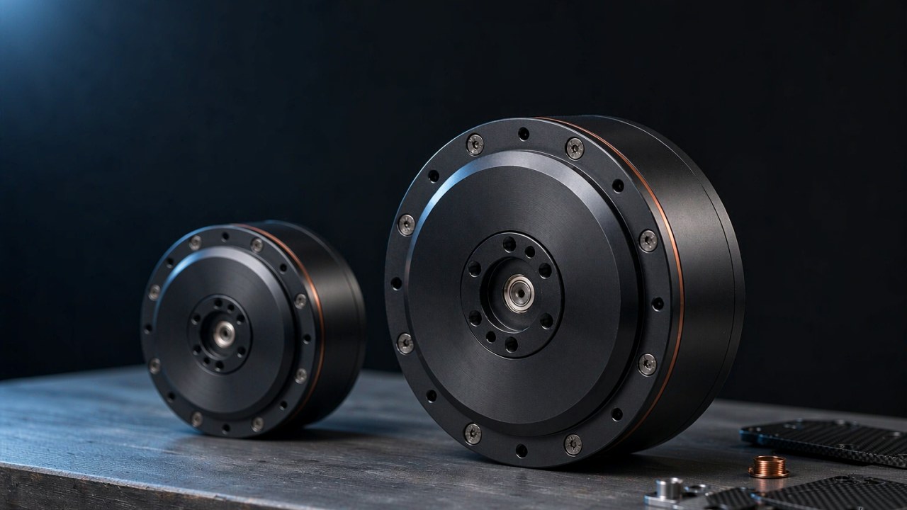
For a legged or manipulator joint behind a planetary stage, a robot joint encoder on the output side is the one that matters, because the transmission is the dominant source of error. The AKH70-48 carries 48:1 and publishes 21 bit on both loops; the AKH70-16 carries 16:1 with the same pair. Encoder resolution on the motor side of a joint like this is secondary to knowing where the output actually sits. Modules in this group are listed under Robotic Actuators, and application context for this class sits with Joint Module.
Wheel drives
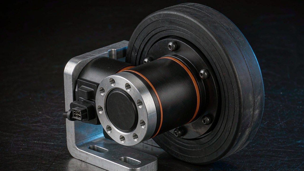
A wheel drive is more forgiving of output angle than a joint, because the load is continuous rotation rather than a held pose. What governs there is the load the hub carries, which is a separate sizing step; radial load at the hub is covered in BLDC Motors for Wheel Robot: Drive Layout, Duty and Gearing. Bus voltage constraints for this class are set out in 48 V Robotic Actuators: Models, Performance Benefits, and System Constraints.
Direct drive and frameless designs
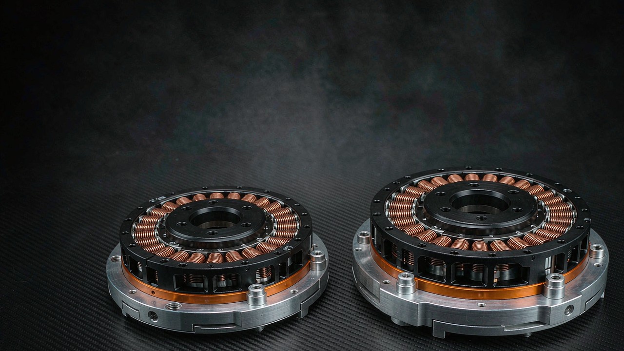
Remove the gearbox and the argument changes. A frameless motor couples the rotor to the load with no reduction, so there is no transmission error to isolate and no ratio to multiply counts by. The RI80 V2.0 frameless inrunner publishes no encoder row at all, with hall sensor integration offered as an option and a rotor height increased by 2 mm to suit hall sensor alignment. CubeMars describes the frameless configuration as leaving support flanges, drive interfaces and encoder mounts to the machine designer. The sensor becomes a machine design decision rather than a module specification, and encoder resolution becomes a property of the encoder the designer fits.
Modules in the quasi direct drive group, including the AKE50-8, are listed under Quasi Direct Drive Actuators, and the frameless range under Frameless Torque Motors. A wider comparison of frameless models is available in Frameless Torque Motors: 12 Models Compared, From Entry to Performance Tier.
Frequently asked questions
How much encoder resolution does a robot joint actually need?
Enough that one count is finer than the error the rest of the chain introduces, and no more. In a geared joint with 12 arcmin of backlash, the transmission slack is around 0.2°, which is far coarser than the step any of the sensors in this range produce at the output. Once encoder resolution is much finer than the slack, extra bits alone are unlikely to change what the joint can repeat.
Does higher encoder resolution make a joint more accurate?
Not by itself. Encoder resolution sets the smallest change a sensor can report; accuracy at the load is decided by backlash, compliance, friction and thermal state. A finer sensor on the motor shaft measures the motor more precisely while the output stays free to sit anywhere inside the backlash band.
What is the difference between a single encoder and a dual encoder?
A single sensor on the motor shaft lets the controller infer output position by dividing motor angle by the ratio. A second sensor on the output shaft measures output position directly. The AK70-9 V3.0 publishes two encoders at 21 bit each; the AK70-10 KV100 publishes one at 14 bit, with the outer ring rows empty.
Does an absolute encoder remove the need to re-home a joint after power loss?
It removes the need to re-home the shaft it measures. CubeMars states that output position is retained after power loss on the AKH70 pair and the AK70-9 V3.0, which both carry output-side sensing, but the published rows for those modules do not state whether the sensor is absolute or incremental. A module with only a motor-side sensor cannot make the same claim about the output, because the state of the transmission after a power cycle is unknown to it.
How much does backlash take away from encoder resolution?
Backlash does not reduce encoder resolution; it sits outside it. The published backlash figures in this range run from 9 arcmin on the AKE50-8 to 18 arcmin on the AK70-9 V3.0, against output-side steps in the region of 0.000172° for a 21-bit output sensor. The slack is the coarser number by orders of magnitude, so it is the one that sets what the joint can repeat.
Specifying feedback comes after specifying the module: torque, ratio, mass and bus voltage first, then the sensor that measures what is left. Encoder resolution should not be optimised in isolation: it belongs with the target positioning performance, the feedback location, the transmission characteristics and the control architecture. For applications that need fine low-speed control or a known output angle at power on, the feedback architecture is a requirement in its own right rather than a final detail. Modules can be filtered by those mechanical figures in Select and compared side by side in Compare Products. A broader treatment of integrated joint modules is available in Robotic Actuators: How to Choose the Right Integrated Actuator for Robot Joints.