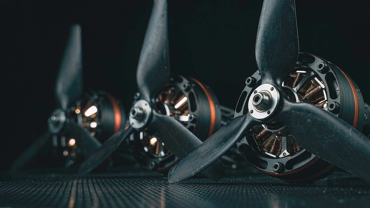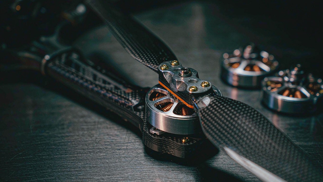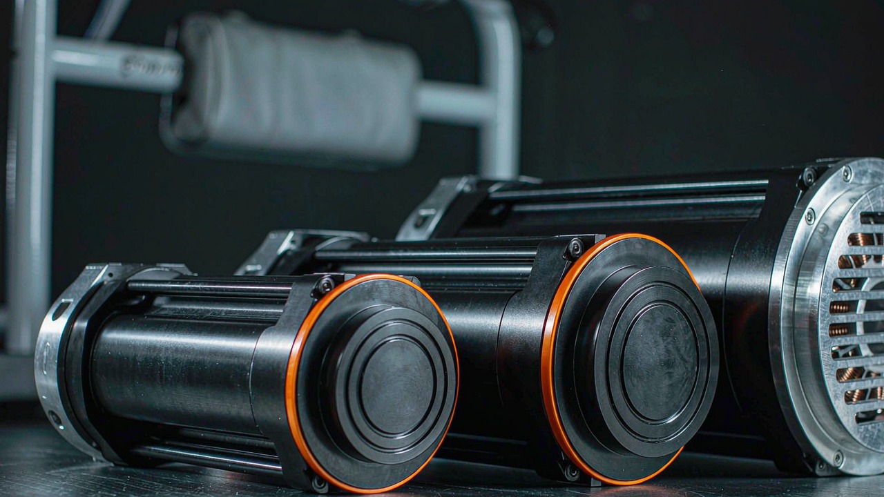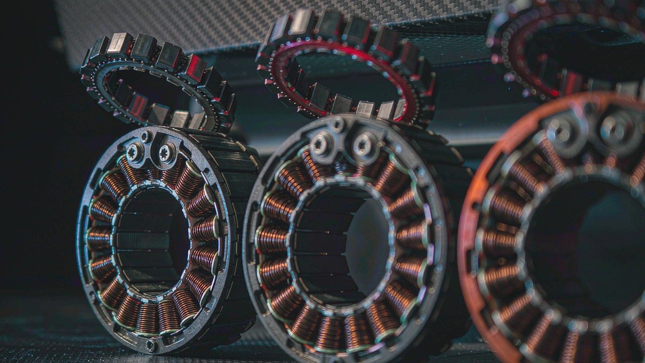
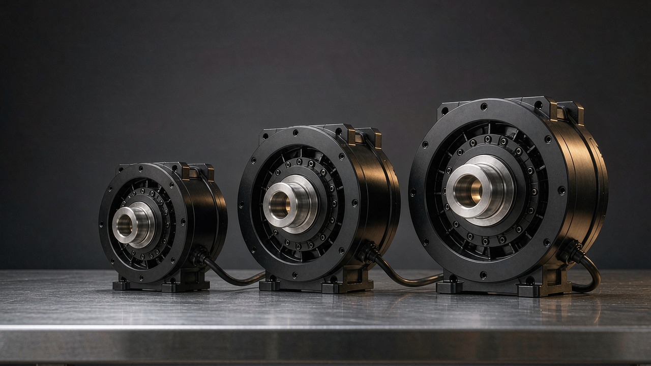
An exoskeleton actuator answers a harder brief than an ordinary robot joint. It has to carry its own energy supply, it sits beside a person rather than inside a machine frame, and it has to stay safe to move even when the battery is flat. Choosing one is rarely about the biggest torque figure on the page. It is about how much mass a limb is being asked to carry, how much torque the joint can hold continuously without cooking itself, how easily the wearer can drive the joint backwards, and how much speed the gait cycle actually demands. This guide works through three CubeMars modules that span 260 g to 1.4 kg and 12.5 Nm to 170 Nm of peak torque, and explains which specification decides the choice at each joint position.
The three units below share one architecture - a brushless motor driving a planetary stage under field-oriented control - and all three use the same 8:1 reduction. What separates them is supply voltage, envelope and torque class, and those differences map onto hip, knee and ankle - only the bus voltage is shared by two of the three. Every figure in this article comes from the ToBMS product records or the manufacturer's published specification, apart from the unit conversions, which are labelled as derived where they appear; nothing here is estimated, and where a value is not recorded it is marked as missing rather than filled in.
Quick answer
For most lower-limb designs the decision follows joint position rather than any single ranking. The AKE60-8 KV80, at 260 g and 12.5 Nm peak, fits ankle and other distal joints where added mass is felt with every step. The AKE80-8 KV30, at 570 g and 30 Nm peak, is the usual starting point for a knee. The AKE90-8 KV35, at 1.4 kg and 170 Nm peak, is the only one of the three sized for a hip that supports body weight directly.
All three belong to a family of QDD actuators, and that is not incidental. A low reduction ratio keeps reflected inertia small, leaves the gearbox comparatively easy to drive from the output side, and lets the joint move when the controller applies no torque at all. Those three properties count far more when the attached load is a person than when it is a robot link, which is why the low-ratio design keeps reappearing in wearable work even when a high-ratio unit would be smaller for the same torque.
What makes an actuator an exoskeleton actuator
The hardware is not exotic. What changes when a joint is worn rather than mounted is the set of requirements that dominates the trade-off.
The load path runs through a person
A robot joint fails machine elements. A wearable joint fails into a body. Every decision - torque limits, speed limits, what happens on power loss, how the mechanism reacts to an unexpected push - has to survive contact with someone who cannot be expected to read a specification sheet first. In practice this pushes three requirements to the top of the list: the device must be back-drivable enough that a wearer can move it unaided, it must not trap a limb if control is lost, and it must behave predictably when the power source is removed mid-stride.
Mass is felt at the limb, not read off a page
Mass is the one specification with a non-linear penalty in wearable work. An extra 400 g carried at the hip is largely supported by the trunk; the same 400 g distal to the knee has to be accelerated and decelerated thousands of times per hour, and published work on loaded walking repeatedly links distal mass to measurable increases in metabolic cost. This is why wearable designs usually chase torque density rather than absolute torque, and why the lightest unit in a range often gets picked for the joint furthest from the body even when a heavier one would be easier to package.
Transparency and back-driveability
Torque transparency - how accurately output torque tracks commanded current - is what makes assist-as-needed control strategies possible. It depends on reflected inertia, friction in the reduction stage, and how much of the motor's own inertia the output sees. A low reduction ratio helps all three at once: it reduces the reflected inertia term, keeps rotor inertia from being multiplied by the square of a large ratio, and generally leaves less friction to compensate. The trade-off is that the same low ratio asks the motor to produce more current per unit of output torque, which is why these modules pair an 8:1 stage with windings in the low tens of KV rather than with a fast winding.
Duty cycle looks like a gait cycle, not a production cycle
Wearable duty cycles have a distinct shape. Peak torques arrive briefly and predictably - push-off, stair ascent, sit-to-stand - while the continuous requirement between those peaks is modest. Level walking typically produces joint angular velocities in the low hundreds of degrees per second at the knee and considerably less at the hip and ankle, whereas rising from a chair or climbing a stair is slow but torque-heavy. An actuator sized against peak alone will be over-built and hot; one sized against the continuous figure alone will stall at the moment assistance matters most. Both numbers have to be considered against the actual cycle.
The six numbers that decide the pick
Specification tables for this class of module are long, but a small number of entries actually move a design decision. These are the six, and how to read each one honestly.
Peak torque is not a working torque
Peak torque describes what the module can produce for a short time. It is useful for transients - the acceleration burst that starts a step, the brief overload of recovering balance - and it is not a figure the gearbox or output bearing has been shown to survive indefinitely. Treating it as a continuous rating is the single most common sizing error in wearable work, and it is usually discovered as a hot housing rather than as a failure.
Rated torque is a thermal statement
Rated torque is the torque the module can hold while staying within its thermal limits under stated conditions. It is therefore sensitive to mounting, ambient temperature and duty shape: a module bolted to a metal link that conducts heat away behaves differently from the same module inside a padded cuff. When an exoskeleton has to hold a posture - supporting a partially loaded limb during standing, for instance - that case belongs against rated torque for the whole holding period, not against peak.
Output speed at the joint, not motor speed
The published speed figures for these modules are quoted at the output flange after reduction, which is what makes them useful directly. Converting them into joint terms is worth doing before any comparison, because degrees per second is the unit biomechanics publications use. Across the three modules: the AKE90-8 KV35 records 120 rpm rated and 210 rpm no-load, or roughly 720 and 1260 degrees per second; the AKE80-8 KV30 records 150 rpm and 195 rpm, roughly 900 and 1170 degrees per second; the AKE60-8 KV80 records 180 rpm and 240 rpm, roughly 1080 and 1440 degrees per second. All three conversions are derived here rather than taken from a datasheet, so the arithmetic is shown rather than hidden.
The interesting detail is the ordering. The smallest module has the highest no-load output speed, because no-load speed follows the winding and the bus voltage before the reduction is applied. Speed is therefore rarely the constraint that separates these three; torque and mass are.
Torque density, quoted both ways
Torque density should be quoted in Nm per kilogram, and always with whether it uses rated or peak torque stated alongside, because the two give very different rankings. Using the recorded figures: the AKE60-8 KV80 delivers about 19 Nm/kg rated and 48 Nm/kg peak; the AKE80-8 KV30 about 21 Nm/kg rated and 53 Nm/kg peak; the AKE90-8 KV35 about 39 Nm/kg rated and 121 Nm/kg peak. The largest module is comfortably the densest by either measure, which is the argument for putting it proximally where the body carries it, even though it is the heaviest.
Supply voltage and the battery to be carried
Two of the three modules are rated at 48 V and one at 24 V, and that split matters more than it looks. Current falls for a given power as voltage rises, so the heavier-current units benefit from wiring looser than a wearable harness really wants to be; conversely, staying on a lower-voltage bus can keep the whole system inside the pack chemistry and connector set already chosen for the device. Mixing 24 V and 48 V units in one garment means two distributions, and usually two driver families.
Backlash and what it feels like
All three modules record the same backlash figure, 0.15. The number should be treated as indicative rather than as a verified manufacturer figure. Backlash in a wearable joint is felt rather than measured: it shows up as a small hysteresis between the commanded assist profile and what the wearer perceives, and it complicates any control law that estimates output torque from position error. Confirm the figure and the test load against the manufacturer's datasheet before designing around it.
Three exoskeleton actuators compared
The table below collects the three modules ordered by mass, which also orders them by torque. Every value is as published in each ToBMS product record.
| Model | Rated Voltage | Reduction Ratio | Rated Torque | Peak Torque | Weight | Envelope |
|---|---|---|---|---|---|---|
| AKE60-8 KV80 | 24 V | 8:1 | 5 Nm | 12.5 Nm | 260 g | Ø69 × 25 mm |
| AKE80-8 KV30 | 48 V | 8:1 | 12 Nm | 30 Nm | 570 g | Ø87 × 32 mm |
| AKE90-8 KV35 | 48 V | 8:1 | 55 Nm | 170 Nm | 1400 g | Ø107.5 × 43.5 mm |
All three modules are listed in the ToBMS Quasi Direct Drive Actuators category. Torque, mass and envelope values are taken from each product record; the 1400 g entry is recorded as 1400. A rated power figure for all three sits with the manufacturer's datasheet, so none is quoted here - that datasheet is the reference where a power budget depends on it. No bore or shaft-dimension field is populated for this series, so no claim about cable routing through the axis is made below.
The first pattern is that mass and torque are not proportional. Going from the 260 g AKE60-8 KV80 to the 570 g AKE80-8 KV30 roughly doubles mass and more than doubles peak torque; going further to the 1.4 kg AKE90-8 KV35 again roughly doubles mass and multiplies peak torque by more than five. Each step up buys proportionally more torque than it costs in kilograms, which is why the largest unit is also the densest.
The second pattern is that the two heavier modules share a 48 V bus while the lightest runs on 24 V. For a lower-limb exoskeleton that draws one module per joint, this determines whether the device needs one distribution or two. It is also why a single-device decision often lands on one supply voltage for every joint even where a lighter unit would fit a distal position better.
The third pattern is axial length. All three are pancake-shaped: every one has a length under half its diameter, with the largest at 43.5 mm and the smallest at 25 mm. That geometry suits joints mounted laterally alongside the anatomical joint, where the dimension that has to be minimised is the one perpendicular to the limb, and it is the main practical reason this family is considered for wearable work rather than for deep narrow housings.
Three AKE modules, three joint positions
The ordering above is by mass and torque. The ordering below is by joint, which is how the decision is usually made in practice.
AKE60-8 KV80 - ankles and distal joints
At 260 g in a 69 mm by 25 mm envelope, the AKE60-8 KV80 is the module whose overview describes it as intended for compact humanoid and exoskeleton joints, and the numbers support that reading. Its 5 Nm rated and 12.5 Nm peak sit comfortably above what an ankle is usually asked for in level walking while staying low enough that the unit does not dominate the distal mass budget. Its 180 rpm rated and 240 rpm no-load - roughly 1080 and 1440 degrees per second - make it the fastest of the three at the output, which gives plentiful headroom over the joint velocities reported during normal gait.
Two details separate it from the others. It is the only one rated at 24 V, so pairing it with a 48 V proximal unit means two rails; it also records 14 pole pairs against 21 on the larger two, which changes commutation requirements and the relationship between electrical and mechanical frequency. A further practical point: recorded rated and peak currents are 4.8 A and 12 A, so the cabling for it is light, and the ToBMS record lists no encoder specifications for this series - feedback resolution should be confirmed directly with the manufacturer.
AKE80-8 KV30 - the knee, and the usual first prototype
The AKE80-8 KV30 is the middle of the range and the module most knee designs start from. Twelve newton-metres rated and 30 Nm peak in a 570 g body leave room for the transient demands of sit-to-stand and stair ascent without committing the design to a 1.4 kg unit at a joint the wearer swings thousands of times per hour. At 150 rpm rated, 900 degrees per second at the output, there is enough speed envelope for swing phase, and its recorded torque density of about 21 Nm/kg rated sits close to the lightest module despite the larger bus voltage.
The manufacturer sequences the AKE modules across compact joint applications, which gives a reasonable sense of how the 8:1 output behaves under hand load and how much difference there is between the lightest and the middle unit when both are seen together.
ToBMS video pageWatch on YouTubeThe 48 V rating aligns it with the largest module, so a device using both needs only one distribution. Recorded currents are 4.8 A rated and 12 A peak - the same as the AKE60-8 despite the higher supply, which is exactly the effect of moving to 48 V. As with the other two units, ToBMS records do not include a rated power figure or a shaft-dimension field, so both a continuous power budget and any through-bore cable plan have to be settled against the manufacturer drawing.
AKE90-8 KV35 - hips and load-carrying joints
The AKE90-8 KV35 is the outlier in this group and the reason the term quasi-direct-drive in this context should not be read as low torque. Fifty-five newton-metres rated and 170 Nm peak in a 107.5 mm by 43.5 mm body at 1.4 kg is roughly four times the rated torque of the next unit down for a little over twice the mass, and it makes this the densest figure among the three by either measure - about 39 Nm/kg rated and 121 Nm/kg peak. Its overview positions it at humanoid legs, exoskeletons and high-dynamic joint modules, and its 120 rpm rated output - about 720 degrees per second - reflects a design biased toward torque.
Two things follow. This is a proximal joint unit: 1.4 kg hung off a knee or ankle defeats its own purpose, while at a hip or a waist-mounted assisting joint the body carries most of it. And its recorded peak current of 72 A, against a rated 21 A, means the power stage and harness have to be sized around the transient, not around the average. Combined with 21 pole pairs and a 48 V bus, this is the module where driver selection and thermal management become genuine design work rather than a formality.
Where these actuators get used
The same three modules appear across several wearable categories, and the pattern of which unit goes where is consistent enough to act as a starting hypothesis.
Lower-limb gait assistance
Hip-knee-ankle assistive devices are the dominant use case for this family. The pattern is proximal-to-distal: AKE90-8 KV35 at the hip, AKE80-8 KV30 at the knee and AKE60-8 KV80 at the ankle. The reasoning is less about each joint's torque demand than about the cumulative metabolic cost of carrying mass distally. Exoskeleton joints are usually specified from the distal end backwards for exactly this reason.
Rehabilitation devices in the clinic
Clinic-based gait trainers and stationary rehabilitation rigs have one advantage: the power supply is not worn. That relaxes the bus-voltage question and shifts the emphasis onto smoothness, back-driveability, and how the joint feels to a patient who may be unable to assist it at all. All three modules appear alongside rehabilitation robot entries in their ToBMS overviews, and the low reduction ratio is the reason they suit work where assist-as-needed control is wanted.
Occupational and industrial support
Lifting-support devices ask something different again: intermittent high torque, long idle periods, and often strict limits on what happens when power is lost. Back-driveability and a transparent reduction stage matter more than continuous ratings here, because the device spends much of its duty at zero torque and then has to deliver a large assist for a few seconds. The joint module family generally suits this application space, and the three units here cover the low-ratio end of it.
Upper limb and shoulder interfaces
Shoulder and elbow support concentrates the hardest packaging problem in wearable work: the joint that needs assistance is close to the body, and anything mounted on it is immediately resented. The 260 g AKE60-8 KV80 and its 25 mm axial length are the closest fit in this range, and its 12.5 Nm peak is generous for elbow flexion. Where a design needs assistance across multiple upper-body degrees of freedom, the wider humanoid robot selection includes options in other form factors.
Selection checklist
Exoskeleton actuator choices are usually locked in early, because the joint geometry and the harness route are designed around them. These checks belong before rather than after that freezing point.
Duty and human factors
- Build the torque-time profile for the actual activity - level walking, stair ascent, sit-to-stand, lifting - and check the sustained part against rated torque, remembering that mounting and clothing change the thermal path.
- Check transients against peak torque, then confirm separately with the manufacturer what the reduction stage and output bearing are rated to survive in shock, since peak is a short-duration figure and not a mechanical limit.
- Establish what the joint must do on power loss, during recovery from a fault, and when the wearer pushes unexpectedly - and confirm that back-driveability supports each case.
Mechanics and mounting
- Fit the envelope to the anatomy before comparing torque: a 107.5 mm body and a 69 mm body are not interchangeable no matter how the numbers read, and 25 mm against 43.5 mm of axial thickness changes whether a unit can sit alongside a joint at all.
- Obtain the maker's mechanical drawing for the output interface. Shaft, bore and thread dimensions for this series sit with the manufacturer's drawing, so bolt patterns and lever arms should be settled from there rather than from the recorded product data alone.
- Plan the harness route as a mechanism in its own right, including strain relief across the joint and what the housing does to the nearest anatomical landmark.
Power and control
- Decide the bus voltage first, from the pack chemistry to be carried, then check which units fit - mixing 24 V and 48 V units means two distributions and usually two driver families.
- Size the driver and harness for peak current while sizing the thermal path for rated current, keeping the two budgets separate - 72 A peak against 21 A rated on the largest module shows how wide that gap can be.
- Confirm feedback resolution, protocol and behaviour on power-up directly with the manufacturer. ToBMS records no encoder specification for this series, and field-oriented control is recorded as the driving method without detail on integration.
Frequently asked questions
QWhat is the difference between an exoskeleton actuator and a regular robotic joint module?
The hardware is similar; the weighting of requirements is not. A wearable joint is judged on mass at the limb, on how it behaves against a human rather than a frame, and on what it does when power is removed. Those three constraints tend to favour a low reduction ratio, a pancake envelope and the highest torque density available, whereas a machine-mounted joint can trade all three away in favour of continuous torque and cost.
QWhich of the three suits a knee joint best?
The AKE80-8 KV30 is the usual starting point. At 570 g with 12 Nm rated and 30 Nm peak it leaves headroom for sit-to-stand and stair ascent without asking the wearer to accelerate 1.4 kg on every step, and its 150 rpm rated output - roughly 900 degrees per second - covers swing-phase speeds reported during normal walking. Where the joint also has to support substantial body weight statically, checking that requirement against rated torque over the holding period comes next.
QWhy do two units run on 48 V while the lightest runs on 24 V?
The recorded figures show the consequence directly: the AKE60-8 KV80 and the AKE80-8 KV30 both record 4.8 A rated and 12 A peak, but deliver 5 Nm and 12 Nm rated respectively. The higher bus lets current stay similar while roughly doubling available torque. For a wearable device the choice is really about the battery pack - a lower-voltage system can stay inside the connector and cell-count already selected for the garment, while 48 V rewards designs that already carry a higher-voltage pack for other reasons.
QCan these modules be back-driven if the power fails?
A low reduction ratio generally leaves a gear train easier to drive from the output side than a high one would, and all three units here use the same 8:1 stage. That said, actual behaviour under power loss depends on the driver electronics and how they behave unpowered, and any such figure sits with the manufacturer's datasheet for this series. The requirement matters enough in wearable work to be confirmed with the manufacturer and then tested on the bench with the intended controller.
QHow much backlash do these modules have, and does it matter?
All three record 0.15, so the figure should be treated as indicative. It matters in two ways: it introduces hysteresis between commanded and perceived assist profiles, and it complicates any control scheme that estimates output torque from position error. Confirm the manufacturer's figure, the torque at which it was measured, and whether it is before or after running-in.
QWhy is the largest module also the densest?
Because torque grows faster than mass across these three. The AKE60-8 KV80 records about 19 Nm/kg rated, the AKE80-8 KV30 about 21 Nm/kg, and the AKE90-8 KV35 about 39 Nm/kg - nearly double the middle unit. Dense output does not make it the right choice everywhere: 1.4 kg is uncomfortable distal to the knee, whatever its torque per kilogram. Density is the argument for placing it proximally, not for placing it everywhere.
QWhat does the ToBMS record not tell me about these three?
Three things in particular. No rated power figure is recorded for any of the three, so continuous power budgeting has to come from the datasheet. No shaft, bore or thread dimension is recorded, so the mechanical interface cannot be drawn from the recorded product data. And no encoder specification is recorded for this series, so feedback resolution, protocol and multiplication should be confirmed with the manufacturer before a controller is chosen. Where a value is missing it has been left out of this article rather than filled in.
Official resources
CubeMars publishes a specification page for each module, and those pages - rather than third-party summaries - are the reference for thermal ratings, feedback details, mechanical drawings and current firmware. The manufacturer pages for the units discussed here are the AKE60-8 KV80, the AKE80-8 KV30 and the AKE90-8 KV35, with the full series listed on the quasi direct drive category page. Where a ToBMS record is silent - rated power, interface dimensions, feedback specification, backlash unit - those pages or the corresponding datasheet are the place to close the gap.
Where to go next
To move from reading to a shortlist, three tools work in sequence: the whole family sits in the Quasi Direct Drive Actuators category, candidates can be narrowed by torque, voltage and mass in Select, and chosen units can be set against each other in Compare Products. Where a design needs the motor integrated into the link rather than delivered sealed, the Frameless Torque Motors category is the alternative route that many wearable programs eventually consider.
Two ToBMS guides extend sideways from here. The Quasi Direct Drive Actuators: What an 8:1 Ratio Buys You goes through what an 8:1 stage changes mechanically, and the Choosing a Joint Module: Five CubeMars Actuators from 190 g to 1.4 kg covers the wider sealed-module families around these three. For comparisons beyond a single series, BLDC motors for exoskeletons collects the recorded matches across the whole range, and the rehabilitation robot page covers the closely related clinical devices.
The short version: pick the joint position first, fit the envelope to the anatomy, size rated torque against the gait duty cycle within thermal limits and peak torque against the transient case, then fix the bus voltage around the battery pack the wearer will actually carry. Most remaining properties of an exoskeleton actuator follow from those four.