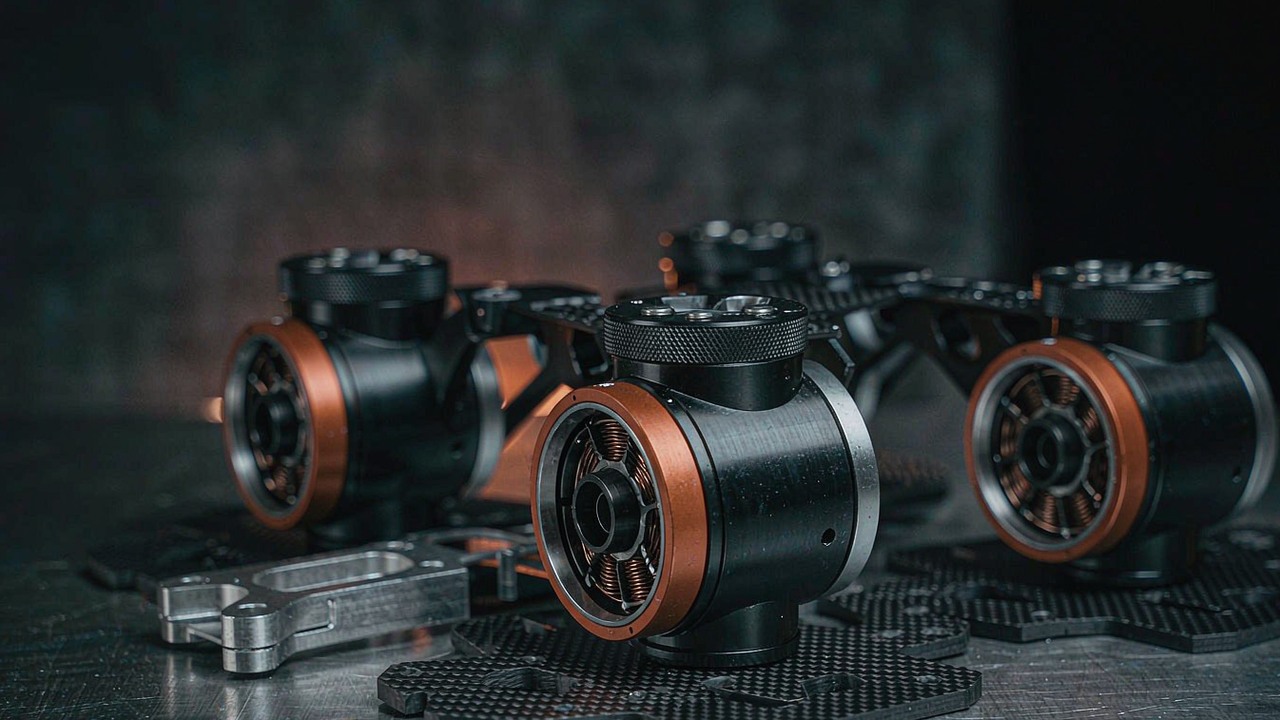
A leg is not an arm that happens to point at the ground. A robot arm is sized against a payload and a cycle time, and most of the time it is either moving or waiting; a Quadruped Robot leg carries the mass of the machine through every stride, spends much of that stride holding torque while barely rotating, and then has to reverse direction several times a second without ever getting to cool down. Those three facts take the usual motor shortlist - torque, speed, envelope, mass - and reorder it, because the constraint that decides whether a machine can trot for twenty minutes is not the peak torque a joint can reach for a fraction of a second but how much heat the winding has already stored by the time the next transient arrives. Choosing a BLDC motor for quadruped robot joints therefore starts from the gait, moves through the three kinds of torque a leg asks for, and arrives at the thermal limit last, because that is where the duty is actually decided.
Quick Answer
A quadruped leg asks three things of its joint motor that a wheeled or fixed-base machine does not. During stance the joint supports body weight while rotating slowly, which is a continuous-torque duty with almost no mechanical power leaving the shaft and therefore almost no help from airflow or motion in moving heat out of the winding. During touchdown and push-off the same joint sees an impulse several times the standing load, arriving through the reducer and reversing direction with each stride. And there are usually twelve of these actuators inside one body shell drawing from one battery, so a per-joint number has to be read alongside what the other eleven are doing at the same instant. A quadruped joint motor is therefore picked from the Robotic Actuators class - motor, planetary stage, feedback device and drive in one bolt-on housing - because the alternative, a bare frameless kit, leaves the integrator to solve the shock load, the sealing and the heat path from scratch.
The shortlist that follows reads five CubeMars actuators associated with the Quadruped Robot application as one specification set, ordered from a 380 g unit to a 960 g unit. The bound that separates them in practice is not the torque column but the rated current next to it, because rated current is what a leg pays for continuously, and the gap between rated and peak torque decides how much reserve is left for the transient when that reserve is already partly spent.
What a Quadruped Leg Asks of a Joint Motor
The three constraints below are not features added on top of a normal motor specification. They move the binding constraint away from maximum output and onto sustained output, which is why a shortlist drawn from peak torque alone tends to produce a machine that can stand up, take a few steps, and then fold.
Four legs share the load until one of them does not
A quadruped at rest divides its weight across four legs, so the standing torque at each knee is roughly a quarter of the machine's mass acting through the leg's moment arm. That comfortable picture changes the moment the machine moves. In a trot - the gait most legged platforms use at speed - diagonal pairs leave and land together and there are intervals with only two feet down, and in a walk there are intervals with three. Even in a standing trot the load is not shared evenly, because the legs nearest the centre of mass carry more and the front-to-back distribution depends on where the payload and the battery sit. The consequence for the motor is that the working torque during a stride is not a quarter of the machine weight; it swings between roughly a third and more than half depending on the gait and the instant, and the peak of that swing is the transient the joint has to survive twice per leg per stride. A budget built on the static four-legged case is not conservative enough to be useful, and the swing between shared and single support is what separates the duty of a quadruped robot leg from the duty of a joint that only ever has to hold its own share.
Stance is a stall, and swing is an acceleration
Each joint in a leg sees two quite different halves of the cycle. In stance the foot is on the ground and the body travels over it; the knee flexes and extends a little, so joint angular speed is low while joint torque is high and sustained. In swing the foot is in the air and nothing is supported, so torque drops to whatever the leg's own inertia demands while angular speed rises to whatever the cadence requires to place the foot before touchdown. A separator built from those two halves has a nasty property from the motor's point of view: the high-torque half is the low-speed half. Mechanical power is torque multiplied by speed, so during stance the joint delivers very little useful mechanical power while drawing close to full current - and in a winding, current squared multiplied by resistance is heat regardless of whether any of it reaches the output shaft. Stance is therefore the thermal case, and swing is barely a thermal event at all.
Touchdown and jump arrive as impulses through the reducer
A trotting machine spends part of each stride airborne, and every landing converts vertical momentum into a force spike at the foot that propagates up through the linkage to the joint. The same happens in reverse at push-off and again during a jump or a recovery step. Those spikes are several times the standing load and they arrive with the gearbox already loaded, which puts them through the gear teeth before the motor sees them divided by the ratio and further reduced by whatever compliance the stage has. Two things follow. First, the motor's peak torque column is not the limit that matters here, because a planetary stage rated for repeated shock loads is a different purchase from one rated for smooth output. Second, the sequence matters: a peak figure published for a cold motor at the start of a test is not the same figure ten minutes into a trot, when the same joint has already stored heat from every prior stance phase and the damping from the leg structure is warmer and softer than it was.
Twelve modules sit inside one body shell
A conventional quadruped has three powered joints per leg - abduction or adduction at the hip, flexion or extension at the hip, and flexion or extension at the knee - so twelve actuators share one chassis, one battery and one thermal volume. That multiplicity changes how every per-unit number should be read. A rated current that looks modest for one module is twelve times as large at the pack, and continuous draw at that level is an endurance figure as much as a thermal one. Heat rejected into a sealed body shell accumulates, because twelve warm modules raise the local ambient for all of them and every downstream unit's rating quietly assumes the ambient its manufacturer tested in. And a common design simplification - using the same module for hip flexion and knee because it halves the spares count - multiplies whatever per-unit decision was made, for better or worse, across eight of the twelve axes.
Torque: The Three Figures a Leg Actually Needs
Three distinct torque quantities appear in a quadruped joint specification and they are routinely confused for each other. Keeping them apart is most of the work of sizing a leg.
Holding torque during stance sets the continuous requirement
The first figure is what the joint needs most of the time: the torque to carry the machine's share of its own mass through the stance phase, with the payload added and with the moment arm taken at the worst posture rather than at the standing one. This is compared against published rated torque, which is the torque a motor can hold indefinitely with the winding staying inside its insulation class. Across the five units below the published rated torque runs from 3 Nm to 18 Nm, and because these are integrated modules the figure is already an output-side figure after the reducer. The trap on this line is to read rated torque against the worst instant of the stride rather than against the average over it; a joint that meets the peak of the stance swing on its rated figure is oversized for the other ninety per cent of the duty and heavier than it needs to be.
Peak torque is a reserve already partly spent
The second figure is the transient: touchdown, push-off, a jump, a slip recovery, or the step onto an unexpected kerb. This is compared against published peak torque, which describes what the motor can produce for a short interval before either the drive reaches its current limit or the magnets begin to lose their working point. In this set the gap between the two is consistent - the peak-to-rated multiple sits between about 2.4 and about 3.0, as arithmetic from the two published columns - so the choice between units cannot be made on that gap alone. What matters more is how much of the gap survives continuous operation. A leg that has been trotting for twenty minutes has used most of its thermal headroom, so the reserve available for the next landing is smaller than the figure on the page, and the size of that reduction depends on a duty window the records below do not publish.
Torque density is charged twice at the knee
The third figure is the one that costs nothing to read and everything to get wrong. Published peak torque per unit mass across these five units runs from about 23.7 Nm/kg on the 380 g unit to about 50 Nm/kg on the 960 g unit, and rated torque per unit mass from about 7.9 Nm/kg to about 18.8 Nm/kg - both arithmetic on the recorded columns, and both rising steadily with size. The rising shape is tempting, because it suggests the larger unit is simply the better one. It is not, for two reasons. First, the peak figures arrive through different ratios, and a ratio buys torque by spending speed; the low-ratio alternative makes that trade visible from the other direction. Second, and specific to a leg, mass placed at the knee is carried by the hip above it and accelerated by it through every stride, so a knee module pays its mass twice: once as inertia the hip has to move, and once as torque the hip has to hold up. On a machine where the knee and hip already use the same module, adding mass to both is the decision that most quickly eats the payload budget.
Backlash and where the impulse goes
Published backlash is the figure most often skipped in a leg, and the most informative one to read. The platform records it in degrees of lost motion at the output, and in this set it runs from 0.2° to 0.38°, with one record carrying no figure at all. That number sets how far the joint can move under load before the gear train takes up, which during a landing is the difference between the controller's estimate of where the foot is and where it actually is. A tight figure costs something elsewhere - usually in efficiency and in shock tolerance - so the useful reading is not "smallest is best" but "smallest that still survives the repeated landing impulse". The AK70-10 KV100 record carries the tightest figure in this set at 0.2°; the AK60-6 V3.0 KV80 record carries none, and that gap belongs on the written set of questions to the manufacturer rather than in an assumption.
The manufacturer's factory footage for the gear trains used across the robotic actuator range, including all five units compared here. It is the most useful reference in this guide for reading the backlash column: the number is a property of how the teeth are cut and assembled, and this is the process that produces it.
ToBMS video pageWatch on YouTubeSpeed: Reading the Published Figure on the Right Side of the Reducer
Speed is where an integrated module is easiest to misread, because the same column means two different things depending on which side of the stage it was measured on, and the record does not usually say which. There is a check that settles it.
Which side of the stage the figure sits on, and how to check
KV is a motor-side constant: the rotor speed per volt of bus, before any reduction. Multiply it by the rated supply voltage, divide by the published reduction ratio, and the result should land on or near the published no-load speed. For all five units below it does. The AK60-6 V3.0 KV80 gives 80 multiplied by 24 V, divided by 6:1, which is 320 rpm against a published 320 rpm, and the same multiplication at 48 V gives 640 rpm against a published 640 rpm. The AK80-8 KV60 gives 60 multiplied by 48 V divided by 8:1, which is 360 rpm against a published 360 rpm. The AK10-9 V2.0 KV60 gives 160 rpm and 320 rpm at 24 V and 48 V against published figures of exactly those values, and the AK70-10 KV100 and AK80-9 V3.0 KV100 land within a few per cent of theirs. The published speed columns for these modules are therefore output-side figures, already divided by the ratio, and the same is true of the rated speed beside them. A joint requirement written in degrees per second can be compared directly against them by multiplying revolutions per minute by six.
What a gait cadence asks for in joint speed
Translating a stride into a joint requirement is mostly a matter of how far the joint travels and how long it has to travel in. Swing has the tighter deadline: the foot has to be placed before touchdown, and at cadences above roughly two strides per second there is well under half a second to do it. Knee and hip excursions during swing are commonly tens of degrees rather than the triple-digit figures an arm might use, so the resulting requirement is often met comfortably by even the slower units - the AK10-9 V2.0 KV60 publishes 109 rpm rated at 24 V, which is about 654 degrees per second, and even that figure exceeds what most walking gaits ask of a knee. The exception is recovery: slipping off a kerb, catching a trip, or executing a jump all ask for a much faster excursion, and that is the case that decides the top end of the speed column. Read against the five records, output speed at rated runs from about 654 degrees per second on the 960 g unit to about 2940 degrees per second on the 380 g unit at 48 V, which is a factor of four and a half and almost entirely explained by the ratio each one carries.
Why faster costs torque
The ratio sitting between the rotor and the output is what couples the two requirements, and it couples them in opposite directions: output torque comes from motor torque multiplied by the ratio and by stage efficiency, while output speed comes from motor speed divided by the ratio. A joint that needs both more torque and more speed than a given module offers cannot get them from the module; it needs a different ratio, a different bus voltage, or a different unit. The five below make that visible as a pattern. The 6:1 unit is the fastest and the least torque-dense. The 9:1 and 10:1 units sit in the middle on both axes. The pair that reaches the highest rated torque does so with the same 9:1 stage as a much lighter unit, meaning the torque came from more motor rather than from more ratio - which is why it weighs 960 g and draws 10.6 A to make 18 Nm where its lighter sibling draws 3.8 A to make 3 Nm.
Thermal Limits: What Decides How Long a Gait Can Run
Thermal behaviour is the constraint that separates a joint that works on a bench from one that works for a shift, and it is the part of a quadruped specification that most often goes unwritten. Five observations carry it.
Zero mechanical power does not mean zero heat
Returning to stance: the joint is producing torque at low speed, so mechanical output is small, and yet current in the phases is close to the continuous limit. In a brushless winding the loss that matters is copper loss, and copper loss is set by current, not by how much of that current is doing useful work. A stance phase is therefore a period in which nearly all the electrical power entering the motor leaves as heat, and efficiency - useful output over input - collapses towards zero at exactly the moment the machine is leaning hardest on the joint. Any thermal model that infers heating from mechanical work will therefore under-predict it badly, and the right proxy in the absence of a thermal resistance figure is the continuous current the record publishes.
Rated current is the working thermal number
Read that way, the current columns are more informative than either torque column. Published rated current across the five units runs from 3.8 A to 12 A, and dividing each by its own rated torque gives a rough cost in amps per newton-metre of continuous output - about 1.27 A/Nm on the AK60-6 V3.0 KV80, about 1.33 A/Nm on the AK80-9 V3.0 KV100, about 0.69 A/Nm on the AK80-8 KV60, about 0.87 A/Nm on the AK70-10 KV100 and about 0.59 A/Nm on the AK10-9 V2.0 KV60. All five figures are arithmetic on two published columns and all five are output-side, so they carry the efficiency of each stage within them rather than isolating it. Even so, the spread is close to a factor of two and a bit, and it does not track mass: the lightest unit has among the highest current cost per newton-metre, which is the signature of a low ratio asking the motor itself to do work a higher ratio would have done with more leverage. For a battery-powered machine this column converts directly into endurance, and for a tethered one it converts into how much heat has to leave the body.
Twelve joints draw from one budget at once
Multiplying the rated power column by twelve gives the order of magnitude a machine has to plan around, and the answer is uncomfortable. All twelve axes standing at continuous rated output would draw about 888 W if every unit were the 74 W AK60-6 V3.0 KV80, about 2760 W if they were the 230 W units, about 4416 W if they were the AK80-9 V3.0 KV100, and about 5160 W if they were the AK10-9 V2.0 KV60. No quadruped sustains that, and the numbers are not predictions - they are the scale against which the real duty cycle should be read, and they explain why the working duty of nearly every fielded machine is a small fraction of continuous rating with brief excursions. The same arithmetic applied to mass is less alarming and more useful: twelve units at the 490 g figure come to 5.88 kg of actuator alone, before structure, battery and payload, which is why the light end of this table exists at all.
Peak into a warm winding is a smaller number
The interaction between the two torque windows is where the thermal limit actually bites. A peak torque figure is a statement about a motor that started within its ambient range; the same joint thirty seconds into a trot has a winding closer to its insulation limit, and the margin between its present temperature and that limit is what is left for the transient. Because stance heating is continuous and stride-repetitive, a leg reaches a steady temperature plateau rather than recovering between steps, and the plateau is reached within a few minutes rather than over an hour. The practical consequence for a BLDC motor for quadruped robot joints is that the peak column should be de-rated for steady-state operation, and the amount to de-rate by is exactly what the manufacturer has to be asked, because none of these five records publishes a duty window, an ambient assumption or a mounting condition for its thermal figures.
Where the heat actually leaves
An integrated module has one heat path available to it: conduction through its own housing into whatever it is bolted to. There is no fan, no airflow worth speaking of inside a sealed leg, and during stance no self-induced motion to distribute the heat either. The practical consequence is that the same actuator behaves like two different products depending on whether it is bolted into a thin polymer shell or clamped into a machined aluminium knee block acting as a heatsink, and the difference is large enough to dominate the choice. This is the one requirement in this guide that is met outside the motor entirely, and it is also why the manufacturer's thermal figures - taken on a test rig, in still air, in a mounting arrangement the integrator will not reproduce - cannot be treated as predictions without a conversation.
Five CubeMars Actuators as One Specification Set
The table below reads five CubeMars robotic actuators as one specification set, ordered by mass, because mass is the axis a leg is engineered along: every gram added at the knee is paid for at the hip above it. Every figure is the manufacturer's published value taken from this platform's product records, and every derived figure in the surrounding text is labelled as arithmetic. Note that two of the five publish operating points for both 24 V and 48 V, and that the published speed figures are output-side - already divided by the reduction ratio, as shown above.
| Model | Reduction Ratio | Rated Torque | Peak Torque | Rated Current | Output Speed | Weight |
|---|---|---|---|---|---|---|
| AK60-6 V3.0 KV80 | 6:1 | 3 Nm | 9 Nm | 3.8 A | 233 / 490 rpm | 380 g |
| AK80-9 V3.0 KV100 | 9:1 | 9 Nm | 22 Nm | 12 A | 390 rpm | 490 g |
| AK80-8 KV60 | 8:1 | 10 Nm | 25 Nm | 6.9 A | 243 rpm | 570 g |
| AK70-10 KV100 | 10:1 | 8.3 Nm | 24.8 Nm | 7.2 A | 148 / 310 rpm | 621 g |
| AK10-9 V2.0 KV60 | 9:1 | 18 Nm | 48 Nm | 10.6 A | 109 / 228 rpm | 960 g |
Published reduction ratio, rated and peak torque, rated current, output speed at rated torque and mass, for five CubeMars robotic actuators associated with the Quadruped Robot application. Rated torque is the continuous figure within the motor's thermal limits; peak torque is a short-window figure. A single speed figure means a 48 V unit; paired figures are 24 V then 48 V. A duty window, an ambient assumption, a mounting condition and a thermal resistance behind either torque figure sit with the manufacturer's datasheet rather than in the record, and the same is true of the backlash figure for the AK60-6 V3.0 KV80.
Three things stand out when the five are read together. The first is how little the torque ordering tracks the mass ordering. The 570 g unit publishes more rated torque than the 621 g unit and nearly as much peak, because its 8:1 stage and its 230 W rating sit differently from its neighbour's 10:1 stage and 230 W rating; two identically-powered units land on different parts of the torque-speed curve because the ratio differs. Mass alone is therefore a poor proxy for capability in this family, and the ratio column is what explains it.
The second is what the current column says about cost per newton-metre. The two densest units on torque - the 570 g and the 960 g units - are also the two cheapest per newton-metre of continuous torque, at about 0.69 A/Nm and about 0.59 A/Nm, while the lightest unit is among the most expensive at about 1.27 A/Nm. The pattern follows the ratio rather than the size: a tall ratio lets a small motor hold a given torque on less current, and the saving does not come free, since it is paid for in output speed and in how much load each landing puts through the stage.
The third is how the arithmetic of power and speed does not fully reconcile for two of the five. Multiplying rated torque by rated speed and converting gives a figure within about one per cent of the published rated power for three units - the AK80-9 V3.0 KV100 at 368 W, the AK10-9 V2.0 KV60 at 430 W, and the AK60-6 V3.0 KV80 at 74 W against its 24 V operating point - but lands about 11 per cent above the published figure for the AK80-8 KV60 and about 17 per cent above it for the AK70-10 KV100 at 48 V. Those last two gaps are not errors in the arithmetic; they are a sign that the rated power, the rated torque and the rated speed in those records were taken under different conditions, and that is precisely the kind of thing to put in writing to the manufacturer before a joint is sized against them.
Reading the Five Across One Leg
A quadruped leg is a short chain, and the requirement changes along it: abduction and adduction move little against low torque but sit at the top of the chain where their mass is carried; the hip flexion joint carries body weight and drives the stride; the knee combines both jobs and takes the landing. The five units divide along that chain.
The 380 g end: abduction and adduction
The AK60-6 V3.0 KV80 is the smallest unit here at 380 g in a 79 mm diameter, 43 mm long housing, and it publishes 3 Nm rated and 9 Nm peak torque through a 6:1 stage on either 24 V or 48 V, with 233 rpm rated and 320 rpm no-load output at 24 V or 490 rpm rated and 640 rpm no-load at 48 V. Its rated power is 74 W and its rated current 3.8 A, with peak currents published as 10.3 A at 24 V and 11.2 A at 48 V. As a hip roll or yaw axis it fits that role closely on paper: it is the lightest unit here, it is the fastest by a wide margin at about 2940 degrees per second of rated output on 48 V, and an abduction joint moves through tens of degrees against a modest load. The reservations are the two already noted - the highest current cost per newton-metre in the set at about 1.27 A/Nm, and the absence of a published backlash figure. Neither disqualifies it; both are questions to close before ordering.
The 490 g class: knee and hip flexion on a light machine
The AK80-9 V3.0 KV100 weighs 490 g in a 98 mm diameter housing that is only 38.5 mm long - the shortest unit in the set, which matters where two modules sit either side of a thigh link - and publishes 9 Nm rated and 22 Nm peak torque through a 9:1 stage on 48 V, with 390 rpm rated and 570 rpm no-load output, 368 W rated power, 12 A rated current and 0.25° of backlash. Its 490 g at 98 mm makes it the natural candidate for the hip flexion and knee pair on a machine in the twenty to forty kilogram range, where stance torque lands inside 9 Nm and the stride does not have to be fast. The reservation is the current: 12 A rated is the highest in this set, and twelve of them working simultaneously would notionally draw 4416 W, so a machine built on this unit needs a pack and a thermal design that were specified together rather than inherited.
The 570 g class: where the duty, rather than the envelope, decides
The AK80-8 KV60 sits at 570 g in a 98 mm diameter, 43.9 mm long housing and publishes 10 Nm rated and 25 Nm peak torque through an 8:1 stage on 48 V, with 243 rpm rated and 360 rpm no-load output, 230 W rated power, 6.9 A rated current and 0.38° of backlash. Read next to its neighbours it is the most balanced entry in the table and the one whose selection turns on duty rather than envelope. It publishes slightly more rated torque than the 621 g unit below it while drawing slightly less current, and it reaches that torque through a shorter ratio, so it keeps more output speed - 243 rpm against 310 rpm at the same bus, but from only 230 W against the other unit's 230 W, which is the pairing that produces the reconciliation gap noted above. Where a platform wants one part number across hip and knee and is willing to machine its own mounting blocks, this is the unit worth costing first.
The 621 g class: the tightest stage in the set
The AK70-10 KV100 is a 621 g unit in an 89 mm diameter, 50.25 mm long housing, publishing 8.3 Nm rated and 24.8 Nm peak torque through a 10:1 stage on either 24 V or 48 V, with 148 rpm rated and 240 rpm no-load output at 24 V or 310 rpm rated and 480 rpm no-load at 48 V. Rated power is 230 W and rated current 7.2 A. Its distinguishing feature in this set is 0.2° of backlash, the tightest figure here, and its 10:1 stage is the tallest - which together point at a machine whose controller relies on knowing where the foot is without measuring it directly. It also carries the widest ratio between peak and rated torque in this set alongside the lightest unit, at about 3.0, so it has the largest nominal transient reserve; whether that reserve survives continuous operation is one of the questions the record leaves open. The manufacturer publishes a showcase reel of the unit in dynamic robotics, embedded below.
The manufacturer's showcase footage for the AK70-10 KV100, run through repeated high-reversal motion rather than a slow single-axis sweep. The relevant point for a leg is not the speed on display but the duty pattern: reversals at load are the shape a stride takes, and this is the unit whose published backlash is the lowest in the set for a controller estimating foot placement through the joint.
ToBMS video pageWatch on YouTubeThe 960 g end: a heavy machine, or a heavy payload
The AK10-9 V2.0 KV60 is the largest unit here at 960 g in a 98 mm diameter, 61.7 mm long housing, publishing 18 Nm rated and 48 Nm peak torque through a 9:1 stage on either 24 V or 48 V, with 109 rpm rated and 160 rpm no-load output at 24 V or 228 rpm rated and 320 rpm no-load at 48 V. Rated power is 430 W, rated current 10.6 A and peak current 29.8 A, with 0.33° of backlash and dual encoders, which is the arrangement that lets one channel read the rotor and another the output through the stage. It makes its torque differently from the other four: rather than a taller ratio, it uses a larger motor at the same 9:1, and it therefore keeps more output speed than a high-ratio unit of equal torque would. That combination suits a machine in the sixty kilogram class, a platform carrying a manipulator or a sensor head, or any leg whose hip has to extend quickly against load - but at 960 g a set of twelve comes to 11.52 kg of actuator before anything else, which is the number that usually sends a designer back to the middle of this table.
Quadruped Platforms These Leg Actuators Suit
All five units are associated on ToBMS with the Quadruped Robot application, which reflects how narrow the duty is: quadruped leg joints whose binding constraint is repeated stance loading rather than peak output.
Inspection and survey platforms
The largest single group of fielded quadrupeds today walks industrial sites - refineries, substations, construction sites, offshore decks - carrying cameras, thermal imagers or gas sensors. The duty is slow, continuous and long: a machine may be on its feet for an hour at a time, standing frequently to read a gauge, and climbing stairs or stepping over cable runs. That is almost exactly the stance-stall profile described above, which makes rated torque and rated current, rather than peak torque, the sizing figures, and it makes the middle of this table - the 490 g and 570 g units - the usual starting point where the machine sits in the twenty to forty kilogram band.
Research and academic platforms
Legged locomotion research needs joints that can be commanded hard one moment and back-driven the next, with published feedback to close the loop on, and it tends to favour whatever is documented more fully over whatever is optimised more tightly. All five units publish FOC drive, KV, Ke and pole pairs, and the AK10-9 V2.0 KV60 additionally carries dual encoders, so both sides of its 9:1 stage can be read. Where a project is building control rather than building product, that documentation is worth more than the last ten per cent of torque density.
Agricultural and outdoor legged machines
Agricultural ground is the harshest service here: soft soil, slopes, debris and moisture, all of which push stance torque unpredictably and demand sealing at the joint. Those conditions argue against the smallest unit in this set, whose 3 Nm rated figure leaves little margin when a foot sinks, and in favour of the 570 g and 621 g units whose rated torque sits higher for a comparable current draw. It is also the duty where published backlash earns its place, because a leg that steps onto uneven ground does not get to assume its foot landed where the controller expected.
Wheeled-legged and hybrid platforms
A growing class attaches a wheel to the end of each leg, rolling on flat ground and stepping over obstacles. The duty splits in two: long periods of very low torque while rolling, punctuated by short, hard transients when the machine steps. That favours a unit with strong continuous figures and a generous peak-to-rated window over one optimised for either extreme, and experience gathered on the wheeled side of the family transfers well here - the Wheel Robot and AGV applications cover that end of the duty.
A Sizing Sequence for a Quadruped Leg
Three steps carry most of the decision, in this order, because each one narrows what the next has to deliver.
Fix the gait duty before the torque
Write down, before any model number: machine mass including payload, worst-case leg posture and its moment arm, gait and cadence, stance fraction, and how many legs are down at the worst instant. From those, derive the continuous stance torque at each joint, the peak transient at touchdown and push-off, and the joint excursion each phase demands. It is that triple - continuous, transient, excursion - that gets compared against the three columns in this table, and skipping the middle one is how a machine ends up with legs that hold posture and fail on landing.
Fix the bus and the sum over twelve joints second
Choose the bus voltage before comparing units, because several publish different figures at 24 V and 48 V and the comparison changes shape depending on which one applies: the AK60-6 V3.0 KV80 roughly doubles its output speed between the two, and the AK70-10 KV100 and AK10-9 V2.0 KV60 move by similar or smaller factors. Then sum the chosen unit's rated current over all twelve axes and check that against the pack's continuous discharge and against the body's ability to reject the heat. A unit that wins the per-joint comparison can lose the system comparison on this step alone.
Put the ratings basis in writing
Ask the manufacturer, for the shortlisted unit: how long the peak torque figure may be held and how often it may be repeated; what ambient and what mounting arrangement the rated torque and rated power assume; what the peak current limit in the drive is set to; whether the published backlash figure is a maximum or a typical value; and what the thermal resistance from winding to housing is. Four of the five records below publish no duty window at all, two reconcile imperfectly between their own power, torque and speed columns, and one carries no backlash figure, so none of these questions is rhetorical.
Frequently asked questions
QWhy is a quadruped joint not simply a stronger version of a robot arm joint?
Because the high-torque part of a quadruped robot joint's cycle is also the low-speed part. An arm mostly moves its payload, so useful mechanical power is produced while torque is high, and much of the input energy leaves the shaft as work. A leg in stance produces torque while barely rotating, so almost none of the input energy leaves as useful work and nearly all of it leaves as heat. That reverses which column matters: continuous torque and continuous current become the sizing figures, and peak torque becomes a reserve to be spent rather than a headline capability. There are also twelve joints sharing one chassis and one battery, which no arm has to plan around.
QHow is published output speed converted into a joint requirement?
By multiplying revolutions per minute by six, since one revolution is 360 degrees and there are 60 seconds in a minute. The published speed columns for these five modules are output-side - already divided by the reduction ratio - which can be verified by multiplying KV by the bus voltage, dividing by the published ratio, and comparing against the published no-load speed; that check lands exactly or within a few per cent for all five. A gait requirement written as degrees of joint travel within the swing interval then converts to degrees per second and compares directly.
QDoes the peak torque figure hold throughout a long run?
Not at the published value. Peak torque describes what the motor can produce for a short interval from within its operating temperature range, so the headroom for a transient is whatever is left between the winding's present temperature and its limit. Because stance heating is continuous and repeats with every stride, a joint reaches a fairly steady temperature plateau within minutes rather than recovering between steps, and the reserve available at that plateau is smaller than the figure on the page. How much smaller depends on a duty window that none of the five records below publishes, which is why it belongs on the written question list.
QWhat does the reduction ratio decide that the motor record cannot?
The position on the torque-speed curve, and therefore what has to be sacrificed to reach a joint requirement. Output torque is motor torque multiplied by the ratio and by stage efficiency; output speed is motor speed divided by the same ratio. A joint needing more of both cannot get them from one module at one ratio. In this set the 6:1 unit is the fastest and least torque-dense, the 9:1 and 10:1 units sit in the middle, and the 960 g unit reaches the highest rated torque at the same 9:1 as a much lighter module - meaning its torque came from more motor rather than from more gearing, which is also why it weighs what it does.
QHow much does backlash matter in a leg joint?
More than in most other joints, because it sets how far the joint can move under load before the gear train takes up, and in a leg that is the difference between the controller's estimate of foot position and the foot's actual position at touchdown. The units below publish 0.2°, 0.25°, 0.33° and 0.38°, with one carrying no figure. Tighter figures generally cost efficiency or shock tolerance, so the useful target is the tightest stage that still survives repeated landing impulses rather than the smallest number available.
QWhich single figure best separates these five for a battery-powered machine?
Rated current divided by rated torque, read alongside the sum over twelve axes. It converts each unit into a cost in amps per newton-metre of continuous holding capability, which is what stance actually buys, and multiplying it by the machine's stance torque and then by twelve gives the draw the pack has to sustain. On that measure the set spans about 0.59 A/Nm to about 1.33 A/Nm - roughly a factor of two and a bit - and the ordering follows the reduction ratio rather than the mass, so the lightest unit is not the one with the lowest draw.
Official resources
CubeMars publishes product documentation for the actuator ranges collected under the platform's Resources section, and each model has an official page carrying its full specification, performance curve and mounting drawing - the manufacturer's product range is the entry point, and the five actuators in this guide are documented individually, including the AK80-8 KV60 and the AK10-9 V2.0 KV60. The manufacturer remains the source of truth for torque curves, thermal ratings, backlash basis and drive configuration; ToBMS keeps the discovery layer searchable and comparable, and the figures used in this guide are the published values held in the platform's product records.
Where to go next
The closest companion to this guide is BLDC Motors for Humanoid Robot: How to Match Torque, Speed and Size, which reads a different eight units from the same family against a bipedal joint chain - the useful counterpoint here, because a humanoid also has to balance and also has a stance phase, and reading the two together separates the constraints that belong to legged machines generally from the ones that belong to four legs specifically. Robotic Actuators: How to Choose the Right Integrated Actuator for Robot Joints covers the category this selection drew from, and Choosing a Joint Module: Five CubeMars Actuators from 190 g to 1.4 kg approaches the same hardware from the assembled joint rather than the gait.
Where the discussion turns specifically to the ratio, Quasi Direct Drive Actuators: What an 8:1 Ratio Buys You sets out what a low-ratio stage changes in reflected inertia, transparency and back-drivability, which is the trade hidden inside the reduction column of every table here. For the wider context of how the motor classes relate, BLDC Motors: A Complete Guide to Brushless DC Motor Types, Specs and Selection places the integrated actuator among the other categories.
To shortlist rather than to research, filter candidates by torque, voltage, mass and envelope in Select and then place them against each other in Compare Products. Related joint classes are grouped in the platform's quadruped robots, Humanoid Robot, Wheel Robot, Joint Module and Exoskeleton applications. The Robotic Actuators category holds all five units compared here, and the CubeMars page collects the rest of the range.