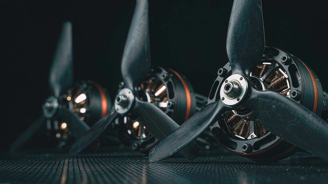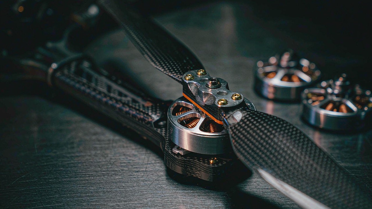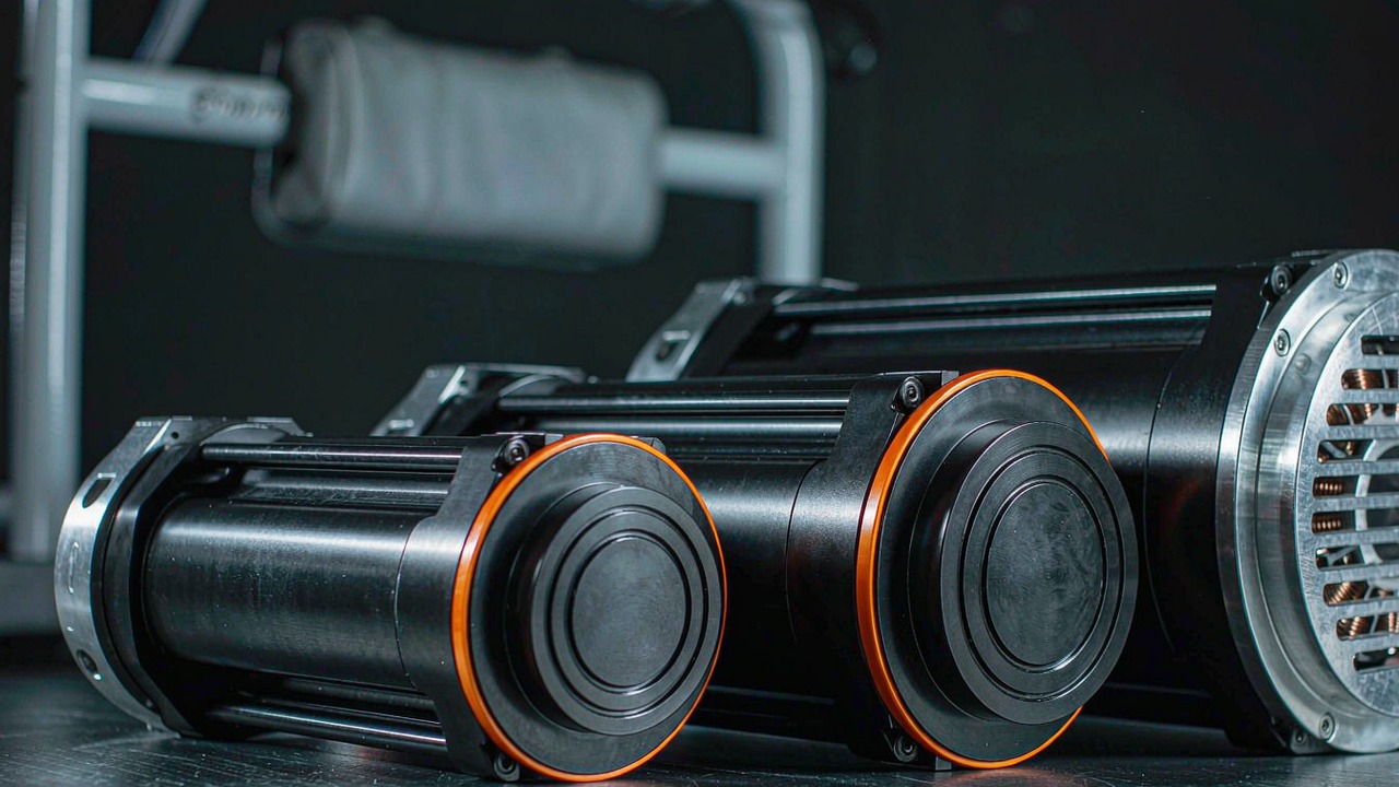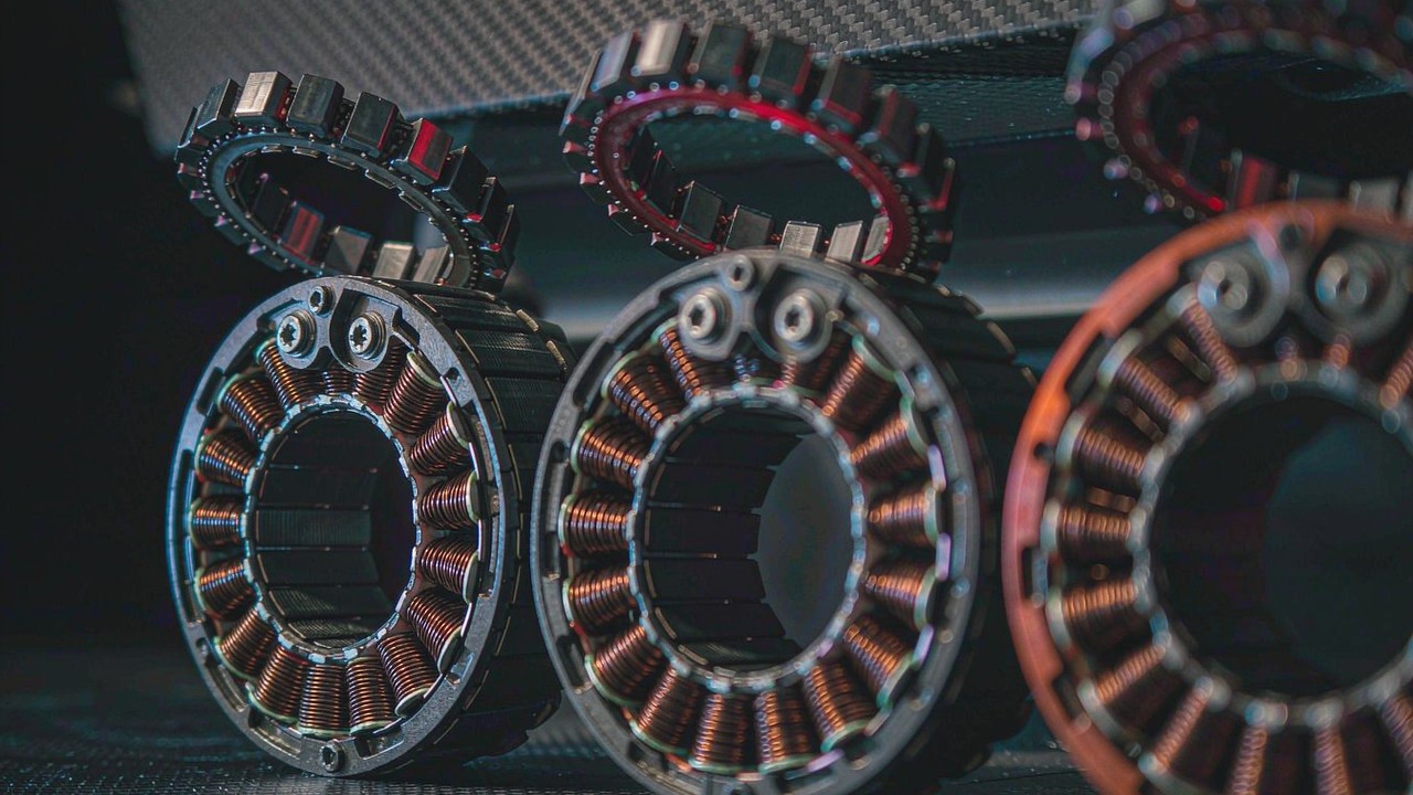
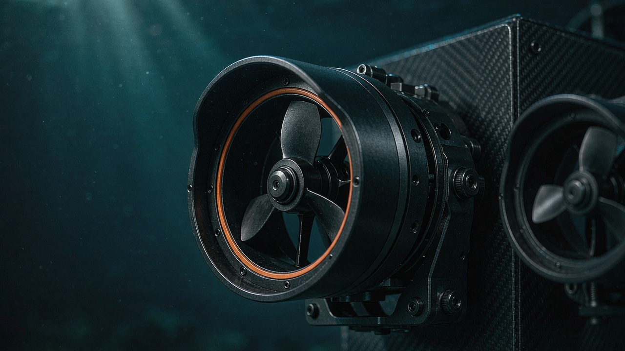
An ROV thruster is not a motor with a propeller bolted to it. It is a pressure boundary that happens to produce thrust, and the engineering order that follows from that is the reverse of an air-cooled drive: the vehicle's load case is fixed first, the sealing concept is fixed second, and only then is the electrical machine chosen to fit inside it. Get that order wrong and the result is usually not a slow vehicle but a flooded one.
This engineering guide works through the five decisions that actually determine whether a thruster suits a vehicle - thrust and power sizing, waterproofing and sealing, the subsea BLDC specification, propeller and Kort nozzle design, and ESC integration - and closes with three failure modes that are particularly important to consider in subsea thruster systems and how each is prevented. Every figure quoted below is either taken from ToBMS product records or from the manufacturer's published specification, and every derived value is labelled as arithmetic on those figures.
Quick Answer
Sizing an ROV thruster starts from the highest steady load the vehicle must hold or overcome - typically station keeping against current with tether drag included - and works backwards through thrust, rated power and bus current to a unit count and a frame envelope. Depth rating is decided at the same time, because it is a property of the sealing system and the housing and cannot be improved after purchase. Sealing, propeller ducting and drive electronics then follow as consequences of those two decisions rather than as independent choices. The thrusters listed in the ToBMS ROV Thruster application span 7 to 25 kgf, 360 to 1315 W and two depth classes, 0-30 m and 0-350 m, and the figures in this guide are the ones on record in September 2026.
Why an ROV Thruster Is Specified Backwards from an Air Motor
An air-cooled motor is selected against a torque-speed requirement, and the mounting is an afterthought. A subsea thruster inverts that: the mounting and the pressure boundary are fixed by the mission, and the electrical machine is then chosen to live inside them.
The vehicle requirement comes first, the component last
A thruster's published numbers - thrust, rated power, voltage, mass, envelope, depth - are all consequences of a vehicle-level decision that has already been made. That is why two 15 kgf units from the same family can differ in mass, and why a component-first selection process tends to end with a vehicle that is either underpowered at the extremes of its envelope or carrying sealing hardware it never needed.
Ambient pressure is the thermal path
In air, a motor dumps heat into a moving air stream that is a poor conductor but easy to move. Underwater the situation reverses: seawater conducts heat far better than air, but the motor is separated from it by a sealed housing, a winding fill and an air or oil gap. The practical consequence is that a subsea BLDC is usually not limited by winding temperature as quickly as a comparable air motor, but it is limited by everything standing between the winding and the water. The housing is the heat sink, and the housing is also the pressure boundary - which is what makes sealing and thermal design the same conversation.
Zero-speed thrust is the number every sizing calculation starts from
Thrust in this application class is published as maximum mooring thrust: the static figure produced at zero forward speed. That is exactly the condition that matters for holding station, breaking out of a silt bed or starting a manoeuvre against a tether, and it is the highest thrust the unit will produce. As soon as the vehicle moves, thrust falls away as the propeller sees a rising inflow. Any comparison between thrusters - and any sizing calculation - is only meaningful at that same zero-speed condition.
One housing carries motor, drive and propeller
ToBMS records this application class as sealed thrusters with an integrated ESC and bidirectional drive. Practically, that means the commutation electronics share the pressure boundary with the motor, the unit is commanded by a thrust or speed setpoint rather than wired phase by phase, and direction is handled electrically rather than by a reversing mechanism. It also means the current and thermal limits are system limits for the complete sealed unit, not motor limits measured on a bench.
Step 1: Calculate ROV's Thrust and Power Requirements
The sizing calculation is the one part of the process that can be done before any hardware is on the table, and it is the part most often done in the wrong direction - from a candidate thruster outwards rather than from the vehicle inwards.
Build the load case before the component list
List every condition the vehicle must satisfy, and for each one write down the force that opposes it: holding station against a current, transiting between two points, resisting tether pull, holding attitude while an arm or tool applies a reaction, and recovering from a fouled propeller. The largest of these, not the average, sets the thrust requirement. Mission profile matters as much as peak value, because a vehicle that station-keeps for an hour is running its thrusters continuously rather than in manoeuvring bursts.
Drag from current and tether, not from a target speed
Station-keeping demand is dominated by two terms. The first is hydrodynamic drag on the frame and payload, which rises with the square of the relative water speed; the second is tether drag, which grows with cable length, current and the catenary the cable forms. Both scale with the frontal area the vehicle presents, which is why a large instrument package can change the thruster requirement more than a change of thruster model does. Because drag rises with the square of speed, the requirement grows quickly once the design current is raised, and a small reduction in design current buys a disproportionate reduction in thrust and power.
From total thrust to rated power and bus current
Once the total thrust requirement is fixed, rated power follows from the efficiency band the family actually achieves. Across the seven units listed on ToBMS the figure is consistent: between about 18.5 and 23.1 kgf of maximum mooring thrust per kilowatt of rated power, calculated from the published thrust and rated power values. That consistency is useful - it means the power budget can be estimated from the thrust requirement alone, before a model is chosen, and any candidate that falls well outside the band is worth a second look at how its figures were quoted.
Bus current is then arithmetic: rated power divided by bus voltage, at the rated operating point and before cable losses. The two voltage classes in this category give a sense of the scale - the 36 V units at 360 W and 540 W draw around 10 A and 15 A respectively, and the 48 V family ranges from about 11 A at 520 W to about 27 A at 1315 W. Those currents set penetrator rating, cable gauge and, on a battery vehicle, the internal cross-section of the pressure housing.
How many units, and which layout
- Degrees of freedom first: a vehicle with separate horizontal and vertical thrusters controls six axes; fewer units trade agility for mass, cabling and fault paths.
- Failure case second: a vehicle that must complete a dive after losing one thruster needs more units than the thrust arithmetic alone implies, because the survivors have to absorb the lost share without exceeding their own limits.
- Redundancy margin third: the surplus thrust per unit that remains after a single loss is the real measure of how recoverable the vehicle is.
- Model last: with the count and layout fixed, the model is chosen to fit the frame envelope and the power budget.
A worked sizing example on recorded figures
Take a six-thruster inspection vehicle that needs 40 kgf of maximum mooring thrust in total, running on a 48 V bus. Using the efficiency band above - our estimate rather than a manufacturer figure - that requires about 1.7 kW to 2.2 kW of rated thruster power, which on a 48 V bus is roughly 36 A to 45 A in total. Split over six units, the per-unit requirement is about 6.7 kgf.
Two candidates fit that requirement from the shallow end of the range. The SW7, published at a minimum of 7 kgf from 360 W, meets it with a thin margin and consumes 6 × 360 W = 2.16 kW - the upper end of the calculated band, and at about 19 kgf per kilowatt it sits in the favourable part of it. The DW10, published at 10 kgf from 540 W, meets the same 6.7 kgf requirement with room for the control loop to work, but consumes 6 × 540 W = 3.24 kW. Choosing the 350 m unit therefore costs about 1.08 kW and about 840 g of additional propulsion mass for the same vehicle-level requirement. Those are arithmetic on published figures, not a recommendation - the decision belongs to the mission depth.
Step 2: Evaluate Waterproofing and Sealing Technologies
Sealing is where a subsea thruster is won or lost, because it is the one subsystem that degrades continuously, and it fails into a total loss rather than a reduced capability.
The rotating shaft is the only moving joint in the pressure boundary
A sealed thruster has one pressure boundary and one motion to transmit through it. Everything else - housing joints, cable entries, sensor ports - can be made static and therefore straightforward. The propeller shaft is the exception, and it is the reason shaft sealing technology, rather than motor technology, separates one class of thruster from another.
Static face seals, dynamic shaft seals and what each tolerates
Static joints are closed with elastomer O-rings or gaskets in a captured groove, and their performance depends on groove geometry, surface finish and squeeze rather than on movement. Dynamic sealing of a rotating shaft is harder: the seal must hold pressure while sliding against a shaft, and the two common families trade differently. Lip and radial shaft seals are simple and compact but rely on a thin film of water as lubricant, so they wear and are sensitive to silt and to running dry. Mechanical face seals run two lapped surfaces against each other and tolerate higher differential pressure and speed, at the cost of size, alignment tolerance and a higher price. A third approach removes the joint altogether by transmitting torque magnetically through a stationary wall, which eliminates the dynamic seal but constrains the torque the design can transmit.
Pressure compensation, oil filling and what they change
A rigid sealed housing at depth experiences the full external pressure as a differential across its walls, which forces thick sections and heavy end caps. Pressure compensation fills the void with an incompressible fluid and links it to the surrounding water through a compliant membrane or bladder, so the differential across the seals and the housing collapses to near zero. The benefit is a much thinner, lighter housing and gentler working conditions for the seals. The costs are a fluid that has to be compatible with the winding insulation and the electronics, a membrane that has to survive the same depth as the housing, and a maintenance procedure that has to be followed exactly after any intervention.
Corrosion, dissimilar metals and galvanic anodes
Seawater is an electrolyte, so any two dissimilar metals in contact with it form a galvanic cell and the less noble one is consumed. The design consequences are practical rather than exotic: housings are usually aluminium alloy, stainless steel or a polymer composite; fasteners and shafts are chosen to sit close to the housing metal in the galvanic series; metallic contact between different families is broken by insulating washers or sleeves where it cannot be avoided; and sacrificial anodes are fitted on the assembly rather than on individual components so that the least noble material in the whole assembly is the one that is deliberately consumed.
What the depth rating does and does not promise
A depth rating is a statement about the sealing system and the housing, not about the motor, and it is the one figure in this category that cannot be changed after purchase. It should be read as a qualified envelope rather than a burst number: the units listed on ToBMS are published as 0-30 m for the shallow family and 0-350 m for the deep family, and the distinction is a design regime, not a tolerance. A 30 m unit can be operated at 5 m, but a 350 m unit is not simply a reinforced 30 m unit - the sealing concept, the housing architecture and consequently the mass are different. When sizing, the operating envelope should be compared against the rating with margin left for the deepest point of the plan, occasional over-depth, and the pressure transient that comes with a dynamic launch or recovery.
Step 3: BLDC Motor Specifications for Subsea Environments
With the load case and the pressure boundary fixed, the motor is chosen to match the propeller and to survive inside the housing.
kV and torque constant set the propeller match
The velocity constant kV and its inverse, the torque constant, describe the same machine property from two directions: kV gives the speed per volt applied, and the torque constant gives the torque per amp. A subsea thruster turns a relatively large propeller slowly, so it wants a low kV machine with a high torque constant - the same trade seen in direct-drive and gimbal motors. Choosing a high kV motor for the same propeller raises current for the same torque, which raises cable and drive losses, adds heat inside a housing that cannot easily reject it, and shortens the armature life that the sizing was supposed to protect. Where a range is offered across several propeller diameters, the kV should fall as the propeller grows, so the change in loading is absorbed electrically rather than mechanically.
Cogging torque and low-speed positioning
Cogging is the periodic torque ripple produced by the interaction between magnets and stator teeth. In a free-running propeller it mostly shows up as noise and as a small efficiency penalty at low speed; in a vehicle that holds a precise heading at very low thrust it shows up as a limit cycle - the controller command and the ripple fight each other. Slot-pole combinations, magnet skew and stator shaping are the usual levers, and they are fixed at design time, so cogging should be treated as a selection criterion rather than something the drive can tune out.
Position feedback inside a sealed housing
Hall sensors give the drive a coarse absolute position and make reliable starting and low-speed control straightforward, at the cost of a sensor set, a wiring harness and a penetrator inside the sealed volume. Sensorless commutation removes all of that and relies on back-EMF estimation, which works well at speed but becomes weakest at the very low speeds where a station-keeping vehicle spends much of its time. In practice the choice follows the duty: a vehicle that must produce smooth thrust from near zero speed benefits from feedback, while a vehicle that runs at speed benefits from the simpler sealed assembly. Either way the feedback device itself is a component inside the pressure boundary and subject to the same corrosion and thermal environment as the winding.
Winding insulation, fill and the water-cooled case that is not optional
The winding sees its own heat and the housing's, and the only route out is conduction. Insulation class, winding fill and the thermal path from slot to housing therefore matter more than they would in an air-cooled machine, and the housing that removes the heat is simultaneously the part resisting the pressure. That is why a change of housing material or wall thickness is a motor selection change as well as a mechanical one, and why the allowable continuous current should be taken from the manufacturer for the sealed assembly rather than from a bare-motor curve.
Which figures are published for this family
The ToBMS records for this application class carry the system-level figures a vehicle designer needs first: maximum mooring thrust, rated power, rated voltage, mass, envelope and depth rating, and they are the figures behind the ROV Thruster comparison further down. Where a project needs the deeper machine data - kV, phase resistance, torque constant, thermal time constant - that comes from the manufacturer's own product documentation for the specific model, and it should be taken per model rather than inferred from the family. Selection figures and machine data answer different questions, and mixing them up is the usual route to a mismatched propeller.
Step 4: Propeller and Kort Nozzle Design
The propeller is where electrical input becomes thrust, and in this application class it is almost always enclosed in a duct.
Why subsea propulsors are ducted
A duct, or Kort nozzle, is a ring of aerofoil section around the propeller. It produces additional thrust of its own at low advance speeds and improves the flow into the blades, which raises bollard pull - the zero-speed thrust that the sizing calculation is built on - for a given blade diameter and power. The trade is at the other end of the envelope: the duct's own drag grows with speed, so a ducted propulsor is more efficient at low speed and less efficient at high transit speed than an open propeller of the same diameter. For a station-keeping ROV that is a favourable trade; for a long-range survey AUV running continuously at cruise it is not, which is why ducted thrusters and open propellers both persist in the field.
Duct geometry: gap, chord and the trade against top speed
The duct's inner profile, its chord relative to the blade chord, and the tip clearance between blade tip and duct interior all govern how much of the duct's lift reaches the flow as useful thrust. Tip clearance is the most sensitive of the three: too large and the tip vortex leaks through the gap, losing the duct's contribution and adding noise; too small and the assembly becomes intolerant of debris, thermal growth and manufacturing variation. Duct chord sets the balance between low-speed thrust and high-speed drag, so the same propeller in two different ducts is two different propulsors. None of this can be re-tuned on a sealed unit in the field, which is one reason the mounting envelope - the recorded diameter and length of the assembly - belongs in the specification alongside thrust and power.
Blade number, pitch and bidirectional sections
Because these units are bidirectional, the blade section has to work with the flow arriving from either side. Symmetric or near-symmetric sections achieve that at a small penalty in peak efficiency compared with a cambered section optimised for one direction, which is the accepted compromise for a vehicle that needs reverse thrust for braking and for backing out of a confined space. Blade number trades smoothness against drag and weight, and pitch is the single most influential choice: a coarse pitch favours high-speed running and a fine pitch favours bollard pull, exactly as it does on any propeller. The published maximum mooring thrust figure is the outcome of all three decisions, which is why a thrust number should be read as a system result rather than as a motor rating.
Cavitation, depth and the limits of a thrust curve
Cavitation occurs where local pressure on the blade surface falls below the vapour pressure of the water, and it destroys thrust as well as eroding the blade. Two variables govern how close a propulsor runs to that condition: blade loading, which rises with thrust per unit blade area, and ambient pressure, which rises with depth. The consequence is worth stating explicitly for ROV work: a ducted thruster is more cavitation-tolerant at 300 m than at 3 m, because the surrounding pressure suppresses the vapour cavities that a shallow-water run at the same power would allow to form. It also means a thrust curve measured in a tank near the surface is not automatically a conservative description of the same unit at depth - the shallow measurement is the harder case, and it is the case that should be qualified for shallow inspection work where the vehicle operates at full thrust in a few metres of water.
Step 5: Electronic Speed Controllers (ESC) Integration
The drive is not a separate box in this application class. It sits inside the pressure boundary, which changes both what it can do and what its limits mean.
Why the drive sits inside the pressure boundary in this family
ToBMS records this application class as sealed thrusters with integrated ESC and bidirectional drive, which places the commutation electronics inside the same housing as the motor and removes the need for a separate penetrator, a separate sealed enclosure and phase cabling that has to cross the boundary. The vehicle side of the interface becomes a power pair and a command link rather than three phase conductors and a position sensor harness. The design consequence is that the drive has to survive the same thermal and pressure environment as the winding, and that the unit's current and thermal limits describe the complete assembly.
Commutation at low speed and in both directions
Commutation strategy is a system decision, not a drive detail. Sensored commutation gives the controller a position reference at zero speed, which makes smooth thrust from rest achievable and starting torque predictable. Sensorless estimation depends on back-EMF and therefore on speed, so a sensorless unit asked to hold a very low thrust against a current is operating in the region where its estimate is weakest. Bidirectional operation adds a second requirement: the reversal has to be ramped rather than switched, because a propeller and a column of entrained water represent a large inertia and a step command will be met by a current spike. Both behaviours belong in the acceptance criteria for the vehicle, not in the thruster's datasheet.
Current limiting, thermal derating and stall behaviour
The most common protection question is what happens when the propeller stops turning - a tether snagged around the hub, weed, or a silt block. A stalled BLDC behaves like a low-value resistor, so current is limited by the drive rather than by the load, and the drive's response decides whether the unit survives. Useful behaviour is a programmable current limit that folds back quickly, a thermal model that derates the continuous current as the housing warms, and a reported fault that the vehicle's control system can act on - typically by reversing briefly to clear the obstruction rather than by pushing harder. A drive that restores full output after each stall, with no derating and no telemetry, converts a recoverable obstruction into a melted winding.
Control interface, telemetry and tether noise
Once the drive is inside the sealed housing, the only signals that cross the boundary are on the tether, and long cables in seawater are an electrically noisy environment. Differential signalling, galvanic isolation and a robust framing scheme on the command link matter more than raw bandwidth, and pull-up or push-pull logic driven over metres of cable is a common source of intermittent faults that appear only at depth and only on long tethers. Telemetry is the other half: thrust-setpoint, bus current, temperature and fault status are the values that let an operator distinguish a fouled propeller from a failing penetrator during a dive rather than after it.
Top 3 Reasons ROV Thrusters Fail (And How to Prevent Them)
Failures in service cluster around three points. None of them is a motor failure, which is the point worth carrying into a specification review.
1. Water ingress at the shaft seal
A dynamic seal is the only wearing part in the pressure boundary, and it degrades in proportion to how much silt, sand and suspended debris the vehicle works in. The symptom is usually gradual - rising insulation leakage, then erratic commutation, then a dead unit - which makes it easy to attribute to electronics.
- Match the sealing concept to the working environment rather than to the depth alone; an abrasive, sediment-laden harbour is harder on a lip seal than a clean deep water column.
- Protect the seal from the propeller's own debris stream, and keep sacrificial anodes close to shaft and seal hardware so the seal housing is not the metal that corrodes.
- Inspect and renew dynamic seals on an interval set by operating hours in sediment, not by calendar time, and treat every housing opening as a reason to replace them.
- Record insulation resistance as part of a pre-dive check so the degradation trend is visible before the fault becomes a flood.
2. Fouling, stall and a current limit reached
Propellers in the water collect things: tether, fishing line, weed, silt disturbed by the thrusters themselves. A fouled propeller stalls, the drive delivers its current limit into a near-zero-speed rotor, and the winding heats with no airflow and no water flow over the housing because the vehicle is no longer moving.
- Set a drive current limit that the sealed assembly can hold indefinitely, and require automatic fold-back rather than a latched trip.
- Make brief reversal part of the standard response to an obstruction; a bidirectional unit can often clear its own hub without surfacing.
- Keep the vehicle's control system aware of the fault so thrust can be redistributed to the remaining units instead of being held on the stalled one.
- Design the thruster layout so that units do not blow silt directly into each other's ducts in confined spaces - the fouling source is often the neighbouring thruster.
3. Connector and cable-entry failures
The penetrator is the second pressure boundary crossing on a sealed thruster, and on tethered vehicles it is where mechanical load, water and dissimilar metals meet at once. Tether strain applied to a connector, a marginally seated penetrator and a wet connector that was mated in the field are the three most frequent causes.
- Strain-relieve the tether on the frame so that no cable tension reaches the penetrator or the connector body.
- Keep penetrator count as low as the architecture allows; every added feed-through is another sealing interface and another galvanic couple.
- Choose wet-mate connectors only where in-water mating is genuinely required; a dry-mate connector protected by a strain-relieved pigtail is more reliable where the vehicle is always recovered before service.
- Check the connector's own depth and current ratings against the vehicle's worst case, not against the thruster's typical operating point.
The Seven ROV Thrusters Listed on ToBMS, as One Specification Set
The table covers the units currently listed in the ROV Thruster application, ordered by published maximum mooring thrust. Thrust is the maximum mooring figure, power is the rated figure at the stated bus voltage, and envelope is the recorded housing diameter and length.
| Model | Maximum Mooring Thrust | Rated Power | Rated Voltage | Applicable Water Depth | Envelope | Weight |
|---|---|---|---|---|---|---|
| SW7 | ≥7 kgf | 360 W | 36 V | 0-30 m | Ø100 × 125.5 mm | 700 g |
| DW10 | 10 kgf | 540 W | 36 V | 0-350 m | Ø100 × 148 mm | 840 g |
| SW12 | ≥12 kgf | 520 W | 48 V | 0-30 m | Ø130.6 × 151.5 mm | 1180 g |
| DW15 | 15 kgf | 750 W | 48 V | 0-350 m | Ø130.6 × 174.5 mm | 1260 g |
| SW17 | ≥17 kgf | 870 W | 48 V | 0-30 m | Ø130.6 × 163.5 mm | 1350 g |
| DW20 | 20 kgf | 910 W | 48 V | 0-350 m | Ø152 × 182 mm | 1630 g |
| DW25 | 25 kgf | 1315 W | 48 V | 0-350 m | Ø152 × 191 mm | 1790 g |
Maximum mooring thrust measured at zero forward speed, rated power at the stated bus voltage, depth rating, envelope and mass as published by the manufacturer. The SW series thrust figures are published as minimums rather than as exact values, which is why they appear with a "≥" prefix.
Read as one set, the seven units describe a thrust ladder from 7 to 25 kgf with two depth classes laid across it. Thrust per unit mass climbs with size - about 10.0 kgf/kg at the 700 g SW7, about 11.9 kgf/kg across the DW10 and DW15, and about 14.0 kgf/kg at the 1790 g DW25 - because a larger housing carries its pressure-resisting structure and its duct more efficiently than a small one. For a frame with a fixed mounting envelope, that gradient is the argument for the largest unit the structure can take, provided the power budget and the fault case allow it.
Thrust per kilowatt is the flatter curve and the more useful planning figure: the seven units sit between 18.5 and 23.1 kgf per kilowatt, all calculated from the published thrust and rated power values. Two units share the same 36 V bus at different sizes - the SW7 at 360 W and the DW10 at 540 W - and five share 48 V, from 520 W to 1315 W. Because the efficiency band is narrow, a vehicle's power budget can be estimated from its thrust requirement before any model is selected, and the choice between families then comes down to depth, envelope and mass rather than to a search for a more efficient unit.
The two depth classes are not a size ordering. The SW family runs from 7 to 17 kgf at 700 to 1350 g, and the DW family from 10 to 25 kgf at 840 to 1790 g, so the families overlap across most of the thrust range and the difference at any given thrust is the mass that the deeper sealing regime costs. Between the DW10 and the SW7 the overlap is direct: at a comparable thrust the 350 m unit is heavier and draws more power for the same job. Whether that is worth paying depends entirely on whether the mission ever exceeds 30 m - a question that, as the sealing section above sets out, has to be answered before the frame is drawn rather than after it.
What Each Family Buys at the Vehicle Level
Both families are recorded as sealed units with integrated ESC and bidirectional drive, so the difference between them is the pressure regime and everything that follows from it.
The 30 m three: 700 g to 1350 g
The shallow family is the lighter option at any given thrust and covers the vehicle classes that never leave the top of the water column - tank and flume work, harbour and river inspection, aquaculture and shallow survey. The SW7 is the entry point, with a published minimum of 7 kgf from 360 W on a 36 V bus in a Ø100 × 125.5 mm, 700 g housing; its modest current draw keeps penetrator and cable requirements simple on a micro-ROV whose tether may be the dominant electrical load. The SW12 moves to a 48 V bus with a published minimum of 12 kgf from 520 W in a Ø130.6 × 151.5 mm, 1180 g unit, which is the voltage step that makes longer tethers practical. The SW17 is the largest shallow-water unit at a published minimum of 17 kgf from 870 W, in the same 130.6 mm diameter but 12 mm longer and 170 g heavier than the SW12 - the point at which frame stiffness and mounting hardware become part of the thruster decision.
The 350 m four: 840 g to 1790 g
The deep family carries the pressure regime that offshore inspection, survey and intervention work demands, and its lightest member is the one that changes the shape of a small vehicle's specification. The DW10 delivers 10 kgf from 540 W in a Ø100 × 148 mm, 840 g housing - a 350 m rating in roughly the mass and the diameter of the shallow 7 kgf unit, at the cost of 180 W and a deeper current draw on the 36 V bus. The DW15 and DW20 cover the middle of the range at 15 kgf and 20 kgf from 750 W and 910 W respectively, in Ø130.6 × 174.5 mm and Ø152 × 182 mm housings. The DW25 tops the set at 25 kgf from 1315 W in a Ø152 × 191 mm, 1790 g unit, and it carries the highest thrust-to-mass ratio in the group at about 14.0 kgf/kg. The manufacturer published a dedicated introduction video for it, embedded below.
The manufacturer's introduction to the DW25, showing the sealed unit running in water. Because thrust figures are published as static mooring values, footage of the unit actually moving water is the most direct way to judge how a 25 kgf rating translates into vehicle motion.
ToBMS video pageWatch on YouTubeWhere the two families overlap in thrust
The overlap is the part of the range where the engineering decision actually happens. At roughly 10 kgf the choice is between a 36 V deep unit and a 36 V shallow unit that differ mainly in mass and current; at 12 to 17 kgf the shallow family competes on mass with deep units of similar thrust; and above 17 kgf the deep family is the only option in this set. Read alongside the worked sizing example in Step 1, the practical rule is that the family is chosen by the mission depth and the model by the thrust requirement - reversing that order produces either surplus sealing mass or an operating envelope that has to be respected for the life of the vehicle.
Where These Thrusters End Up Working
Every unit in this application class is associated on ToBMS with the same application, which reflects how specific the duty is: the ROV Thruster application covers vehicles for which propulsion is the primary design constraint rather than an accessory.
Inspection and observation vehicles
Inspection-class vehicles hold position against a current while an operator studies a structure, a hull or a pipeline, which means their thrusters run continuously rather than in manoeuvring bursts. Continuous duty is what makes the thermal path through the housing the binding constraint, and it is the duty where the efficiency band matters most: a unit that produces more thrust per kilowatt leaves more of the available power for lighting, cameras and sensors.
Work-class and intervention vehicles
Intervention work adds a reaction load that has nothing to do with water flow - a manipulator pushing against a structure pushes the vehicle back, and the thruster set has to hold attitude while it does. That requirement is met with thrust margin distributed across more units rather than with larger units, which is where the fault case in the layout decision becomes the dominant term. Depth class is decided here: offshore intervention work is the reason the 350 m family exists, and the extra mass per unit is the price of the regime.
AUVs, hybrids and battery-powered platforms
A vehicle that carries its own battery has to carry it inside a pressure-rated housing, which makes voltage architecture a mass decision as well as an electrical one: a higher bus draws less current for a given power, which means thinner conductors inside the housing and a smaller penetrator. The 48 V units in this set cover 520 W to 1315 W, so a battery vehicle with a multi-unit layout is usually designed around that bus. Where the same vehicle also runs on a tether for long station-keeping periods, the ducted, bidirectional architecture of these units suits both modes without a change of hardware.
Shallow-water and tank work
Pool, flume, harbour and river work is where the shallow family is the correct answer rather than a compromise, and it is also the regime where cavitation behaviour deserves attention for a different reason: ambient pressure is lowest in the top few metres, so a ducted propeller run at full power close to the surface is operating closest to its cavitation limit. That makes the shallow duty a harder case to qualify than a deep one, and it is an argument for keeping thrust margin at the shallow end of the envelope rather than spending the whole budget on station-keeping capability at depth.
Frequently asked questions
QHow is the thrust requirement for an ROV calculated?
From the largest steady load the vehicle has to hold or overcome, which is normally station keeping against the design current with tether drag included, plus whatever reaction load any tool or arm imposes. Hydrodynamic drag rises with the square of relative water speed and tether drag rises with cable length and current, so both terms scale with the frontal area the vehicle presents. Published thrust is a zero-speed mooring figure, so the transit case has to be calculated separately. The total is then divided by the efficiency band for the family - 18.5 to 23.1 kgf per kilowatt across the units listed on ToBMS - to give the rated power, and divided again by bus voltage to give the current the tether, penetrator and supply have to carry.
QWhat does a Kort nozzle change about thrust?
It raises bollard pull - the zero-speed thrust used for station keeping - by producing thrust of its own at low advance speeds and by improving the flow into the blades, for a given blade diameter and power. The trade appears at the other end of the speed range, because the duct's own drag grows with speed. That is why a ducted propulsor suits a station-keeping ROV and an open propeller suits a survey AUV running continuously at cruise, and why both arrangements persist in the field rather than one replacing the other.
QWhy is 48 V the common bus for larger ROV thrusters?
Because current, not power, sets cable gauge, penetrator size and conductor cross-section inside a sealed housing. At the rated operating point the 36 V units in this set draw around 10 A and 15 A at 360 W and 540 W, while the 48 V family ranges from about 11 A at 520 W to about 27 A at 1315 W. A higher bus therefore keeps the current manageable as thrust rises, which matters most on a battery vehicle where the conductors sit inside the pressure boundary. The voltage is a system decision rather than a thruster decision, and it should follow the vehicle's power architecture.
QWhat does pressure compensation change in a subsea thruster?
It replaces the pressure differential across the housing with a near-zero one by filling internal voids with an incompressible fluid linked to the surrounding water through a compliant membrane. The result is a much thinner and lighter housing and gentler working conditions for the seals. The costs are a fluid that has to be compatible with the winding insulation and the electronics, a membrane that has to survive the same depth as the housing, and a reassembly procedure that has to be followed exactly after any intervention - so the benefit is mechanical, while the added discipline is procedural.
QHow does depth rating relate to cavitation?
Ambient pressure rises with depth, and cavitation begins where local pressure on the blade surface falls below the vapour pressure of the water. A ducted thruster is therefore more cavitation-tolerant at 300 m than at 3 m for the same power, because the surrounding pressure suppresses the vapour cavities that a shallow run would allow to form. The practical consequence is that the shallow duty is the harder case to qualify, and that a thrust curve measured in a tank near the surface is not automatically a conservative description of the same unit at depth.
QWhy is the rotating shaft seal the most common failure point?
Because it is the only part of the pressure boundary that moves. Static joints can be made sealed and forgotten, but a rotating shaft has to hold pressure while sliding, and lip seals depend on a thin water film as lubricant while mechanical face seals depend on two lapped surfaces staying in alignment. Both degrade faster in sediment-laden water than in a clean water column, and both fail progressively - insulation leakage first, then erratic commutation, then a dead unit - which is why an insulation-resistance reading belongs in the pre-dive checklist and why seal renewal intervals should be set by operating hours in sediment rather than by calendar time.
QIs it worth oversizing an ROV thruster?
Surplus thrust is worth having, but it should be bought as margin in the sizing calculation rather than as a larger unit in the same frame. Extra thrust per unit costs mass, current and power on every unit in the layout, and on a battery vehicle that comes directly out of endurance; extra units cost the same three things but also add fault paths and degrees of freedom, which is what intervention work needs. Where the frame diameter is shared between two models, as it is across the 152 mm deep units in this set, a later upgrade is possible in the same mounting space - which is usually a better way to buy headroom than to carry it from the first dive.
Official resources
CubeMars publishes product documentation covering the SW and DW thruster ranges, collected under the platform's Resources section, and each model has an official product page with its complete specification, performance curve and mounting drawing - the underwater thruster range is the entry point. The manufacturer remains the source of truth for thrust curves, sealing specifications, pressure qualification and drive configuration; ToBMS keeps the discovery layer searchable and comparable.
Where to go next
The component-level counterpart to this guide is Underwater Thrusters: Matching Thrust, Power and Depth Rating, which takes the seven units in the Underwater Thrusters category model by model and reads their published figures against each other. This guide starts one level further out, from the vehicle's load case and pressure regime, and arrives at the same seven units by a different route - useful when the question is what the vehicle needs rather than which model is larger, and when the shortlist has to come out of the ROV Thruster application rather than out of a single model family.
To shortlist rather than to research, the platform tools run in sequence: filter candidates by thrust, voltage, mass and depth in Select, then place them against each other in Compare Products. Where the same sealed architecture is needed for a rotating joint rather than for propulsion, the Robotic Actuators category covers that range.
The short version: fix the load case and the pressure regime first, because neither can be changed after the frame is drawn; convert the thrust requirement into power and current using the 18.5 to 23.1 kgf per kilowatt band; then let envelope, mass and fault case choose between the 30 m and 350 m families and between the models inside them. Sealing, ducting and drive electronics are consequences of those three decisions, not independent choices - and the three failure modes that dominate the field all sit at the pressure boundary, which is exactly where a specification review should end.