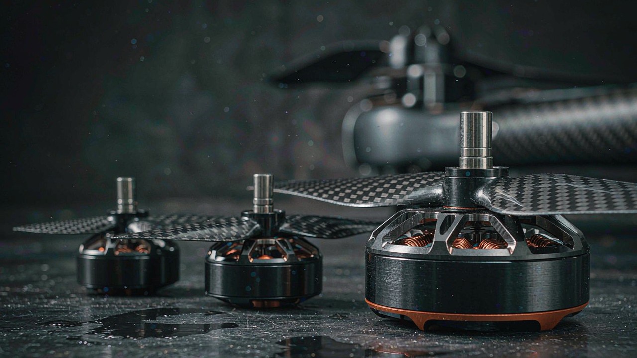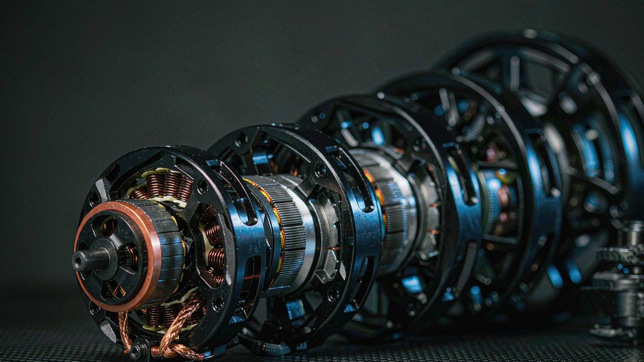
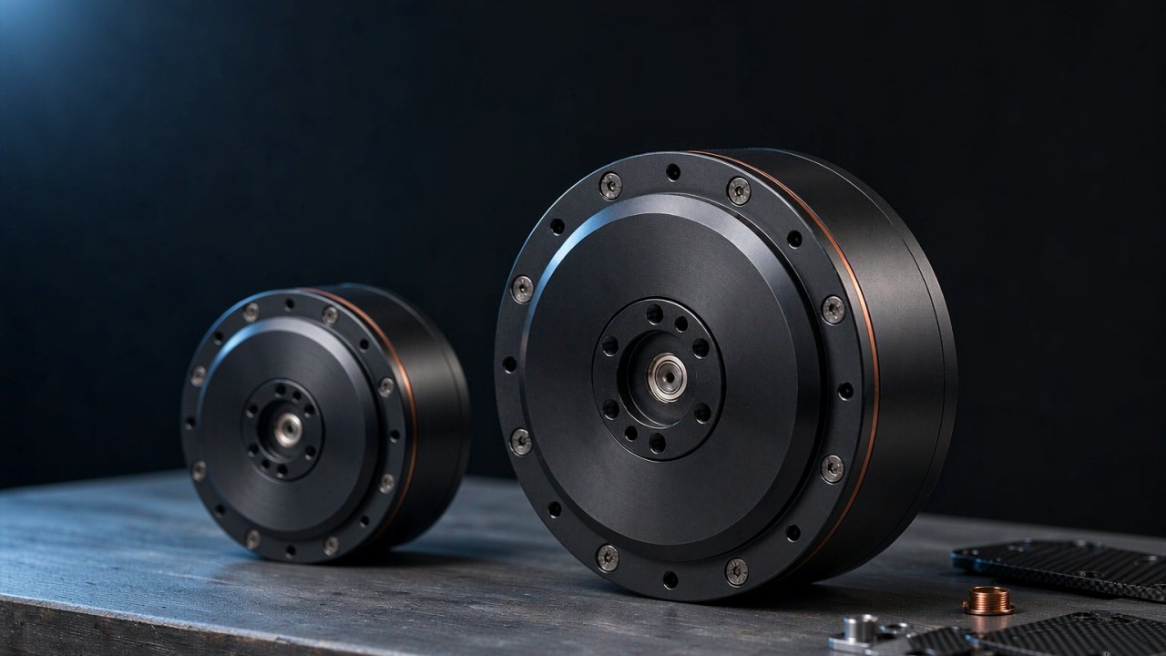
A high torque robotic actuator is an integrated module - a brushless motor, a reduction stage, feedback and a drive in one housing - chosen for the torque a robot joint has to hold rather than for the largest figure on a specification panel. The term carries a boundary that a motor specification on its own does not: a frameless kit sold into the same class of machine may publish a peak torque of a few newton metres and leave the bearing, the encoder and the drive to the integrator, while an integrated high torque robotic actuator for a hip, a knee or a shoulder is published above 100 Nm. The two records compared here - the CubeMars AK80-64 KV80 and the AKH70-48 V1.0 KV41 - sit at 120 and 222 Nm of peak torque in housings of 850 g and 1396 g, and the spread between them follows from three decisions rather than from two quality levels. The boundary between a frameless kit and an integrated module is taken apart in High Torque Frameless Motor: Where the Torque Comes From, and the same duty is described on the Robotic Actuators category.
Quick Answer
The first decision is the hold, not the peak. A robot joint actuator spends most of its life near a standing load - an arm holding a tool, a knee taking a share of the body mass, a leg in stance - and the figure that describes that condition is the continuous, or rated, torque. Peak torque describes a short excursion the module can make without immediate damage, and it is a reserve rather than a working point. A high torque robotic actuator is therefore shortlisted against the standing load first, with the peak figure read as headroom for acceleration, touchdown and balance recovery.
The second decision is the reduction stage, because ratio is what turns a small motor into a joint. The two modules here use 64:1 and 48:1 stages, and the ratio moves output speed and output torque in opposite directions at the same time as it changes how much of the load the joint can feel through the gearing. A high reduction ratio multiplies output torque and reduces output speed. It can also make the joint harder to backdrive because the motor-side inertia and transmission losses affect the motion felt at the output. The actual backdrivability depends on the gearbox design, friction, transmission efficiency, motor characteristics and control state, so reduction ratio alone does not determine how easily an external force can move the joint. A ratio is therefore chosen against a duty rather than against a target number. Reading a high torque robotic actuator means reading the ratio and the winding together, because either one alone leaves the joint undefined. A robot joint actuator built on the wrong ratio cannot be corrected later by changing the winding.
The third decision is thermal, and it is the one most easily skipped. Rated torque is a thermal statement, and it is the manufacturer's specified output torque under stated operating and thermal conditions. Whether it can be maintained continuously in a particular robot depends on factors such as ambient temperature, mounting, heat dissipation, drive settings and duty cycle, so the conditions behind the published rating have to be confirmed with the manufacturer before a joint is sized for sustained loading. The bus voltage sets how much current is needed for a given output power, the winding resistance turns that current into copper loss, and the module then loses the heat through its housing. On the two records here the rated torque is 48 Nm and 74 Nm, and each of those figures is tied to a rated current published beside it - 7 A and 6 A. Selecting a high torque robotic actuator is choosing the pair of torque and current that a duty can live inside, and on a robot joint actuator the pair is what the record publishes, not the torque figure on its own.
What makes a robotic actuator high torque
High torque is a relationship between an output figure and the conditions it was obtained under, and it is not a grade that a module either has or lacks. For a high torque robotic actuator that relationship is stated in the conditions printed beside the torque figures rather than in the figures alone. Three quantities carry most of it: the torque the module holds continuously, the torque it can reach briefly, and the place in the drive train where the multiplication happens. The three sections below take them in that order.
Rated torque is the figure a joint holds continuously
Rated torque is published for a stated bus voltage and a stated thermal condition, and it is the output torque the record specifies for the conditions named beside it. Sitting at that figure for as long as the duty requires is a question about the machine the module is fitted to - ambient temperature, mounting, heat dissipation, drive settings and duty cycle - rather than a property the figure carries on its own. It is bounded from above by the winding rather than by the magnets: the current a winding can carry indefinitely is set by how fast the heat it generates can leave the module, and the module has no active cooling of its own. On the records here the rated torque is 48 Nm on the AK80-64 KV80 at 7 A and 74 Nm on the AKH70-48 V1.0 KV41 at 6 A. The ratios between those pairs differ by more than the torque figures do, which is the first sign that a high torque robotic actuator is selected on the pair and not on the torque alone.
There is also a condition that rated torque does not cover on its own: a joint that holds a pose at zero speed still draws current, and therefore still produces heat in the winding. Mechanical output power is zero at standstill, so a figure quoted as a power rating does not bound the holding case. A robot joint actuator that holds a pose all day is therefore sized on the rated current as much as on the rated torque. The current the winding can carry in that state is still set by the same thermal conditions as the rating itself - ambient temperature, mounting, heat dissipation and duty cycle - and it is further bounded by what the drive can supply and what the load requires. For a high torque robotic actuator the holding case is therefore a current question, but the answer is a figure for a stated set of conditions rather than a level that holds in every installation, and the current is what sizes the drive.
Peak torque is a short excursion, not a working point
Peak torque is published with a peak current and a time window that the record usually states separately, and it is the torque a joint can reach during an acceleration, a touchdown or a correction. The two records here publish 120 Nm at 19 A and 222 Nm at 18 A. Peak torque should be assessed together with peak current, the permitted duration of the excursion and the manufacturer's operating conditions. A robot joint actuator that reaches a high peak torque through a very large current is placing a correspondingly large thermal load on the winding and drawing a correspondingly large current from the drive and the pack, but a lower published peak current does not by itself establish higher efficiency or lower energy consumption, particularly when the compared modules differ in motor design, reduction ratio and rated operating point. A high torque robotic actuator whose record states neither a peak current nor a time window leaves the excursion undefined. A high torque robotic actuator for a joint that reaches its peak often is therefore chosen on the peak current and on how long the excursion lasts, not on the peak torque figure alone.
Where the reduction stage takes over from the winding
The torque at the joint is not the torque at the rotor. A reduction stage multiplies rotor torque by its ratio and divides rotor speed by the same ratio, so a modest motor can produce a large joint torque through a large ratio, at the cost of output speed. This is the split between the two routes a machine builder can take. Increasing a motor's own torque means increasing its diameter, its stack length and therefore its mass; adding reduction means keeping the motor and paying in speed, backlash and backdrivability. A robot joint actuator that has to be backdriven by a person and one that has to hold a heavy load sit on opposite sides of that choice. A high torque robotic actuator is the second of those routes packaged as a unit, and the ratio published with it - 64:1 and 48:1 on the records here - states how far along that route the module has been taken. That is a statement about the principle rather than about the two records set against each other, because the output torque and current each of them publishes also depend on its own motor torque capacity and on the rated operating point its manufacturer chose to state.
Specifications that decide a high torque robotic actuator
The published panel of an integrated module carries more rows than a selection needs. Five of them, taken together, describe the joint the module can serve: the two torque figures, the ratio, the bus and its current, the mechanical envelope, and the thermal statement behind the continuous rating. For a robot joint actuator the useful discipline is to read those five as one set, because a high torque robotic actuator that satisfies four of them and fails the fifth is still the wrong module. The sections below take each in turn.
Rated torque and peak torque
Rated torque and peak torque answer different questions, and the ratio between them is not a quality score for a robot joint actuator. The AK80-64 KV80 publishes 48 Nm rated against 120 Nm peak, a factor of 2.5, and the AKH70-48 V1.0 KV41 publishes 74 Nm against 222 Nm, a factor of 3.0. What those factors describe is the size of the published reserve above the standing load, and it is a ratio between two specification figures rather than a measure of usable control margin or of permitted dynamic performance. A joint whose duty is mostly holding wants the rated figure high relative to the load; a joint that repeatedly accelerates a distal mass wants the reserve, and with it the peak current the reserve is bought with. A high torque robotic actuator is shortlisted by asking which of the two the duty spends.
Reduction ratio and output speed
The ratio sets the joint's speed as directly as it sets its torque. Output speed is motor speed divided by the ratio, so the 48:1 and 64:1 modules reach 28 rpm and 23/48 rpm at their rated points and 35 rpm and 37/75 rpm at no load. The two figures for the AK80-64 KV80 are the same module described at the two bus voltages its record covers. Those output speeds are joint speeds, not rotor speeds, and a robot joint actuator that needs a fast distal axis and one that needs a heavy hold will want opposite ends of that column. The ratio is also the one column that moves rated torque and peak torque together, because it multiplies both on the way out.
Bus voltage and continuous current
The bus voltage is chosen outside the module, and it decides the current the module draws for a given output power more than it decides the torque. A higher bus at a given level of shaft power generally means a lower supply current and therefore lower copper loss, at the cost of a heavier pack and a higher-rated drive. One of the two records here is published for 48 V alone, and the other carries a 24/48 V record with two speeds and two no-load speeds listed against it. The continuous current published with the rated torque is the figure that connects the two, and for a robot joint actuator it is also the figure that sizes the drive stage and the harness. A high torque robotic actuator is published with its bus, and the two are read together. The wider subject of running these modules on a 48 V bus is taken apart in 48 V Robotic Actuators: Models, Performance Benefits, and System Constraints.
Mass, envelope and bore
Mass at a joint is charged for twice on a legged machine, because the segment it sits in has to be carried and accelerated by the joints above it. The two records here span 850 g and 1396 g, in envelopes of 98 × 61.9 mm and 90 × 81.5 mm, and the differences in shape matter as much as the differences in mass: a 61.9 mm axial length and an 81.5 mm axial length are different mechanical envelopes, and which of them fits a given joint depends on the mounting pattern, the space available and the load path rather than on the axial length alone. A robot joint actuator being fitted into an existing limb is constrained by the shape it has to fit as much as by its mass. The bore is a third decision inside the same column - one of the records here publishes a 7 mm hollow bore for cables routed through the joint, which removes a harness loop from a moving limb. A high torque robotic actuator cannot be compared on diameter alone.
Thermal duty and what the continuous rating covers
The continuous rating is a statement about a temperature, and it is worth knowing which one. Rated torque and peak torque are both statements about a winding temperature, and neither is a figure a module can hold for an arbitrary time. Insulation class sets the temperature the winding can reach, and the ambient range published with the module sets the other end of the difference. Both records here publish insulation class H, and operating ambient ranges of -20 to 50 degrees. What a record of this kind normally does not publish is the temperature rise that was assumed, the mounting condition it was measured in, and how the figure changes when the module is bolted to a metal structure that conducts heat away from it rather than sitting in still air. Those are questions for the manufacturer's documentation, and a high torque robotic actuator whose duty runs near its continuous figure is worth confirming there before the joint is committed.
High torque robotic actuator modules above 100 Nm peak compared
The two records compared here are integrated CubeMars modules whose published peak torque sits above 100 Nm, set out as one specification set and ordered by published peak torque so that the step from the lighter joint to the heavier is visible in the column itself. Every value is the figure the manufacturer publishes for that module, and no cell is estimated or converted. Where a record does not carry a field, the table says so rather than filling the gap. Both are candidates for the same family of joints, and each is a high torque robotic actuator for a different point in the duty.
| Model | Reduction Ratio | Rated Torque | Peak Torque | Rated Voltage | Rated Current | Peak Current | Rated Speed | No-load Speed | Weight | Envelope |
|---|---|---|---|---|---|---|---|---|---|---|
| AK80-64 KV80 | 64:1 | 48 Nm | 120 Nm | 24/48 V | 7 A | 19 A | 23/48 rpm | 37/75 rpm | 850 g | 98 × 61.9 mm |
| AKH70-48 V1.0 KV41 | 48:1 | 74 Nm | 222 Nm | 48 V | 6 A | 18 A | 28 rpm | 35 rpm | 1396 g | 90 × 81.5 mm |
Model, reduction ratio, rated torque, peak torque, rated voltage, rated current, peak current, rated speed, no-load speed, weight and envelope as published by the manufacturer for the two integrated modules compared here, ordered by published peak torque. Rated torque and rated current are the pair published together for a continuous duty; peak torque and peak current are the pair published for a short excursion, and the duration of that excursion is a separate condition that this table does not carry. Speed and envelope are output-side figures for the joint, not rotor-side figures. Where two speeds are shown against one model, the record covers two rated voltages and publishes one speed for each, in the order 24 V then 48 V. Weight is published as a single figure for the module including its cables. No separate column repeats the KV figure because each model name in the table carries its own.
Two readings stand out once both are on one page, and neither is the torque column. The first is that a larger peak torque does not cost a larger current. The AKH70-48 V1.0 KV41 publishes 222 Nm of peak torque at 18 A, while the AK80-64 KV80 publishes 120 Nm at 19 A, so the module with nearly twice the peak torque asks a fractionally smaller current. That is a specification observation rather than an efficiency ranking: the two records differ in motor design, KV, package and control as well as in ratio, and each peak figure is a rating point its manufacturer publishes rather than the result of a controlled test at the same joint torque and speed. A 48:1 or a 64:1 stage does multiply rotor torque by the ratio, so the current asked of the winding is set by the rotor torque rather than by the joint torque, but the ratio is only one of the reasons the two records separate. On a joint whose duty is a heavy hold rather than a fast swing, that is the difference that decides the module, and it is not visible in the peak torque column alone. For a high torque robotic actuator the current column is therefore read against the torque column rather than after it.
The second reading is that the two records separate on the ratio rather than on the mass. The AK80-64 KV80 and the AKH70-48 V1.0 KV41 publish 850 g and 1396 g in envelopes of 98 × 61.9 mm and 90 × 81.5 mm, one on a 64:1 stage and the other on a 48:1 stage. At different masses the two occupy different envelope classes, offer different output speeds and draw different currents. That is the clearest reminder in the table that mass is a packaging outcome rather than a description of duty, and that choosing between two high torque robotic actuator records turns on the arithmetic of the joint rather than on the weight.
A third reading concerns the continuous pair. The rated current published beside the rated torque is 7 A on the lighter module and 6 A on the heavier one, and the module with the larger ratio is the one that asks the smaller current. The AKH70-48 V1.0 KV41 publishes a higher rated output torque and a lower rated current than the AK80-64 KV80 in this two-model dataset, and these figures describe the manufacturers' respective rating points rather than a controlled comparison at the same joint torque and speed. A fair comparison of current draw, copper loss or overall efficiency would require operating data under comparable load, speed and thermal conditions. The published pair is still useful for sizing a drive and a pack, and it is also the point at which a joint's thermal duty has to be estimated rather than read, because the rated current is a figure for a stated condition and the condition a specific machine creates is a question for the manufacturer's documentation. A high torque robotic actuator for a duty of that kind is chosen on the pair the record publishes, not on the torque figure alone.
CubeMars AK80-64 KV80: 48 Nm rated at 64:1
The CubeMars AK80-64 KV80 Robotic Actuator opens the group at 850 g and 98 × 61.9 mm, on a 64:1 stage with 48 Nm rated and 120 Nm peak from a 24/48 V record. Its rated current is 7 A against a peak current of 19 A, and its speeds are published for each of its two rated voltages. Its record also carries a 0.18 degree backlash figure, a maximum torque-to-weight ratio of 141.2 Nm/kg, a back drive torque of 4.7 Nm and a single magnetic encoder with a 14-bit inner resolution. The 24 V half of its voltage window is unusual in this group, and it makes the record a candidate where the bus is not fixed. Rated torque, rated speed and no-load speed all change between the two voltages, so the 24 V and 48 V figures have to be read against the drive and the pack the joint will actually use before the module is chosen. Its published mass and envelope are a starting point for a joint whose envelope is tight, and they place the module where it has to fit inside a small joint rather than beside it.
CubeMars AKH70-48 V1.0 KV41: 74 Nm rated at 48:1
The CubeMars AKH70-48 V1.0 KV41 Hollow Shaft Planetary Actuator is the top of the range shown here at 222 Nm of peak torque and 74 Nm rated, from a 48:1 stage on a 48 V record. Its rated current is 6 A and its peak current 18 A, which is the smallest peak current in the group for the largest peak torque. For a high torque robotic actuator the pair of 74 Nm at 6 A is the figure that describes a joint holding a limb in place for hours rather than for moments. It is also the only record here with a hollow bore, published at 7 mm, and the only one with two encoders - a magnetic encoder on the motor side and a second on the output side, both at 21-bit resolution. Its torque density is published at 159 Nm/kg, its backlash at 12 arcmin and its back drive torque at 2.22 Nm. A low back drive torque is a published specification feature, and it is useful for a joint that is meant to resist external movement, but on its own it does not establish the module's design intent or its ability to hold a load safely. The 48:1 ratio and the 74 Nm rated torque are the figures that describe that side of the record, and they have to be read together with the thermal conditions behind the continuous rating. The bore is what separates it from the other record for a robot joint actuator inside a moving limb, and it puts the module forward as a candidate for a legged machine or a heavy manipulator axis rather than settling the choice.
Quasi direct drive stage or planetary stage for a 100 Nm joint
A joint that has to produce around 100 Nm can be built from more than one arrangement, and the choice between them is not a question of which is better. The two records compared here belong to the Robotic Actuators category, and both use a planetary stage. The low-ratio route is a separate family: the Quasi Direct Drive Actuators category holds modules built on a single low reduction stage, and the trade that route makes is taken apart in Quasi Direct Drive Actuators: What an 8:1 Ratio Buys You. What separates the two routes is where the multiplication happens, what it costs in current, and how much of the load a robot joint actuator is allowed to feel.
Where a high-ratio planetary stage wins
The high-ratio stage wins when the joint has to hold a heavy load for a long time and when the current drawn at that hold has to stay small. The 48:1 record here publishes 74 Nm rated at 6 A and 222 Nm peak at 18 A; the 64:1 record publishes 48 Nm rated at 7 A and 120 Nm peak at 19 A. Reading rated torque and peak torque against the currents published with them is how the two records separate on their published figures, and both halves of that pair matter: the rated figure is the hold, the peak figure is the reserve, and the current beside each one is what the winding pays at that rating point. For a given joint torque, a higher reduction ratio can reduce the motor torque required, but the resulting current depends on the motor's torque constant, transmission efficiency and operating conditions. The current ratings of these two different modules should not be treated as a controlled comparison of the current required for the same joint torque. A lower current in the winding would mean less copper loss and less heat to remove from a housing that has no fan, and that is why the ratio matters on a holding duty, but the size of the effect cannot be read off the two rating points compared here. What it gives up is output speed, and it gives up the joint's ability to be moved by an outside force - the 48:1 record publishes a back drive torque of 2.22 Nm against 4.7 Nm for the 64:1 record, both small numbers that describe how much of the load the motor can still feel.
What the ratio does to output speed and heat
The ratio moves speed and torque in opposite directions, and it moves heat indirectly through the current. Because output speed is motor speed divided by the ratio, a high-ratio joint reaches the same joint speed at a much higher motor speed, which for a given back EMF and bus voltage limits how fast the joint can go. Because output torque is motor torque multiplied by the ratio, a high-ratio joint reaches the same joint torque at a much lower motor torque, and therefore at a much lower motor current. The published speed figures illustrate the output-speed differences between these modules: the AKH70-48 V1.0 KV41 lists a rated speed of 28 rpm and a no-load speed of 35 rpm, while the AK80-64 KV80 lists 23/48 rpm rated and 37/75 rpm at no load for its 24/48 V ratings. These speed figures should be read separately from the published peak-current ratings unless the manufacturer provides test data linking them to a specific operating point. They describe different robot joint actuator duties rather than different grades of the same one. A high torque robotic actuator is not selected by asking which arrangement is superior, but by asking which of those two combinations the joint's duty actually spends its time in.
Matching a high torque robotic actuator to a joint duty
The three steps below apply the columns in the order that turns a joint duty into a shortlist. These are the same columns a high torque robotic actuator is judged on, taken in the order a duty constrains them. On the records here they also lead to the Joint Module application page, where the same duty is described with its own filter attributes.
Start from the worst-case hold, not the cruise
The worst-case hold is the standing load the joint has to keep in place for the longest unbroken time, and it sets the continuous requirement. For a knee it is the share of the body mass the joint carries through single support; for a shoulder it is the tool held at the end of a fully extended arm; for a hip it is the heavier of the two. Those are starting values rather than fixed requirements, because the centre of mass, the moment arm, the posture the joint works in and the dynamic loads the segment carries all change the torque the joint has to produce. That figure is compared against the published rated torque, not against the peak, and the current published beside it is compared against what the drive and the pack can supply for the same duration. The published rated torque and peak torque pair is read here at the rated end, and a robot joint actuator matched on its peak figure will run hot on a hold of this kind. On the records here the rated figures are 48 Nm and 74 Nm, and a joint whose worst-case hold sits above the one it was matched to cannot be rescued by a later step.
Then the speed at that torque
Speed and torque are published on opposite sides of the same trade, so the second step fixes the joint speed the duty needs and reads the ratio that produces it. Output torque, output speed, backdrivability and thermal duty are read together rather than in a strict one-way order, so the ratio that the first step appears to have settled is revisited here against the speed the duty needs. A distal axis that has to track a fast trajectory wants a low ratio and the output speed that comes with it; a proximal axis that has to carry a load slowly wants a high ratio and accepts a low output speed. The two records here reach 35 rpm and 37/75 rpm at no load, a range narrow enough that a joint needing a fast distal axis will fall outside it. A high torque robotic actuator whose ratio was chosen before the speed requirement was fixed will usually have to be replaced rather than retuned.
Then the thermal duty cycle
The third step is the one that decides between two modules that both pass the first two. A duty that holds a load continuously spends the rated current for most of the cycle; a duty that accelerates a distal mass repeatedly spends the peak current more often than the average suggests. The two records here publish rated currents of 7 A and 6 A and peak currents of 19 A and 18 A, and the gap between the two figures is where a duty cycle either fits or does not. The duty cycle is the last column, and for a high torque robotic actuator it is often the one that decides between two modules that pass the first two steps. What the records do not publish is the temperature rise behind the continuous figure, the mounting condition it was measured under, and the ambient the joint will actually see. Those are questions for the manufacturer's documentation, and the honest move is to put them there rather than to infer an answer from a neighbouring record.
The three steps applied to this group give a shortlist rather than an answer:
- A joint with a tight envelope and a bus that is not fixed. The AK80-64 KV80 is the 850 g record at 64:1, with a 24/48 V window and 48 Nm rated against 120 Nm peak. It is a candidate where those conditions match, and the operating point and thermal duty still have to be checked for the specific joint.
- A joint that has to hold a heavy load for long periods. The AKH70-48 V1.0 KV41 is the 48:1 record at 1396 g, with 74 Nm rated at 6 A, 222 Nm peak at 18 A and a 7 mm bore for cable routing. It is a candidate on that duty, and the thermal condition behind the continuous rating is the point to confirm with the manufacturer before the joint is committed.
Frequently asked questions
QWhat is a high torque robotic actuator?
A high torque robotic actuator is a packaged joint module that combines a brushless motor, a reduction stage, and - in the integrated form - feedback and a drive in one housing, and that is published for output torque above the level a small frameless kit reaches. The term describes a class rather than a threshold: the records compared in this guide publish 120 Nm and 222 Nm of peak torque, while a frameless stator-and-rotor kit sold for the same machines is often published at a few newton metres and leaves the bearing, the encoder and the drive to the integrator. What makes a high torque robotic actuator selectable, and what makes a robot joint actuator of this class usable, is not the peak figure on its own but the pair of rated torque and rated current that sits under it.
QWhat is the difference between rated torque and peak torque on a robot joint actuator?
Rated torque is the output torque the manufacturer specifies for a stated bus voltage and ambient, and it is published together with the rated current that goes with it. Sustained holding at that figure depends on the thermal conditions behind the rating - ambient, mounting, heat dissipation and duty cycle - so the figure describes a defined set of conditions rather than an unlimited ability to hold the load. Peak torque is a short excursion the module can reach during an acceleration, a touchdown or a balance correction, and it is published with a larger peak current and, in most records, a time window. On the records here the two pairs are 48 Nm at 7 A against 120 Nm at 19 A, and 74 Nm at 6 A against 222 Nm at 18 A. The peak figure is a reserve, not a working point, and a joint sized against the peak will run hot.
QHow is actuator torque matched to a robot joint duty?
Three steps, in order. First, the worst-case standing load the joint has to hold for the longest unbroken period is compared against the published rated torque and the current beside it. Second, the joint speed the duty needs is compared against the output speed the ratio produces, because torque and speed sit on opposite sides of the same ratio. Third, the duty cycle - how much of the time the joint spends holding and how much accelerating - is compared against the gap between the rated current and the peak current. A robot joint actuator that passes all three steps is a candidate; the thermal condition behind the continuous figure and the mounting it was measured under are separate questions for the manufacturer's documentation.
QHow does reduction ratio change the torque a high torque robotic actuator delivers?
The ratio multiplies rotor torque on the way to the joint and divides rotor speed by the same factor. A 48:1 stage therefore turns a modest motor torque into a large joint torque at a low output speed, where a 64:1 stage produces a lower joint torque from a similar motor and reaches a slightly higher output speed. The records here show the arithmetic in current rather than in torque: 222 Nm peak at 18 A on a 48:1 stage against 120 Nm peak at 19 A on a 64:1 stage. A high torque robotic actuator therefore cannot be compared on ratio alone: within one module the ratio moves three quantities at once - output torque up, output speed down, and the load the joint can feel from outside down with it - but the difference between two records also depends on each motor's own torque capacity, its transmission efficiency, the current it is permitted and the rated operating point its manufacturer published.
QDoes a 48 V bus raise the torque of a robotic actuator?
It does not raise the torque directly; it changes the speed the module can reach and the current it draws for a given output power. KV is rpm per volt, so at a fixed KV a higher bus raises the speed ceiling, and for a given shaft power a higher bus generally means a lower supply current and therefore lower copper loss in the winding. The speed columns in the table above show the effect of a two-voltage record: the AK80-64 KV80 publishes 23/48 rpm rated and 37/75 rpm at no load for its 24/48 V window. What a higher bus does not change is the reduction ratio, the envelope, or the rated torque and peak torque the module itself is published for, and it brings with it a heavier pack, a higher-rated drive and a different set of insulation and connector questions.
QWhich robotic actuators reach 100 Nm peak torque or more?
Among the records compared in this guide, two integrated CubeMars modules sit above 100 Nm of published peak torque: the AK80-64 KV80 at 120 Nm and the AKH70-48 V1.0 KV41 at 222 Nm. Each is published with its own rated torque and peak torque pair, its own current pair, a ratio and an envelope, and the two cover different joint duties rather than two steps of the same one - a 24/48 V module at 850 g and a 48:1 hollow-shaft module at 74 Nm rated. A joint whose standing load sits above the top of that range is outside what these two records cover and needs a different arrangement.
Official resources
CubeMars publishes an official product page for each module with its specification panel, and those pages remain the source of truth for every figure quoted in this guide - for example the AK80-64 KV80 product page and the AKH70-48 V1.0 KV41 product page. The torque, current, speed, ratio, weight and envelope figures in the table above are the values those pages publish for each module. A temperature rise behind a continuous rating, the mounting condition a figure was measured under, a field a record does not carry, or the length of a peak excursion is a question for the manufacturer's documentation rather than a value that can be derived from the specification panel.
Where to go next
For shortlisting rather than reading, three tools on the platform do the work in sequence. Explore the full Robotic Actuators category to see these modules alongside the lighter joints in the same range, use Select to narrow by ratio, rated torque and published envelope, then place candidates against each other in Compare Products. The Joint Module application page holds the same duty with its own filter attributes, and the Quasi Direct Drive Actuators category covers the low-ratio arrangement.
Two further articles carry the parts of a joint selection that a module comparison does not settle. Robotic Actuators: How to Choose the Right Integrated Actuator for Robot Joints takes the integrated module apart from the inside - motor, reduction stage, feedback and drive - and is the reference for what arrives inside the housing. 48 V Robotic Actuators: Models, Performance Benefits, and System Constraints follows the bus decision through the drive, the pack and the connectors, which is the step that sits between choosing a high torque robotic actuator and making it run in a machine.
The short version: fix the worst-case standing load first, because it is the only figure the joint holds for long; fix the ratio second, because ratio sets output torque and output speed at the same time and cannot be adjusted afterwards; read the bus and the rated current together third, because the bus changes the current and the current is what the winding has to live with; and confirm the thermal condition behind the continuous figure last, with the manufacturer, because that is the one column a specification panel rarely carries. Within this group that sequence separates the 850 g 64:1 record from the 48:1 hollow-shaft module before any individual joint is weighed against another.