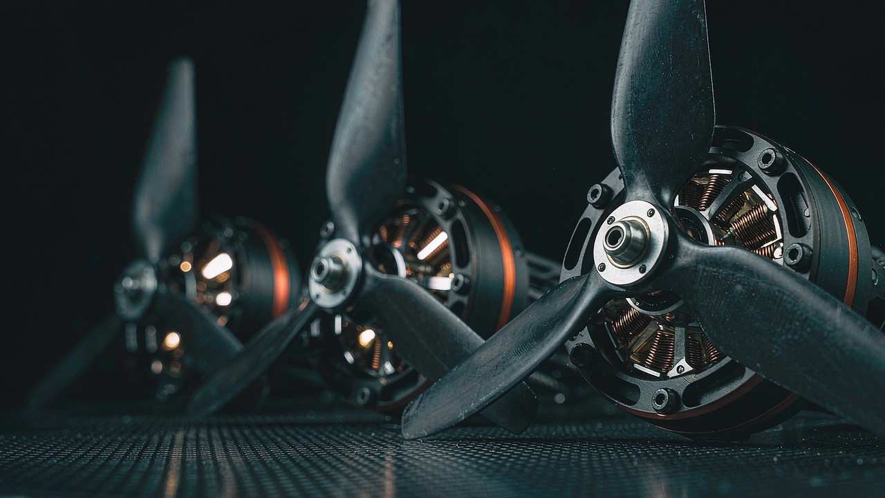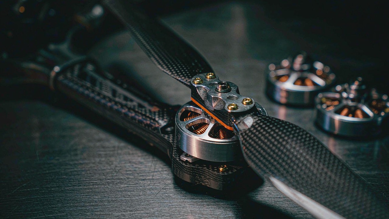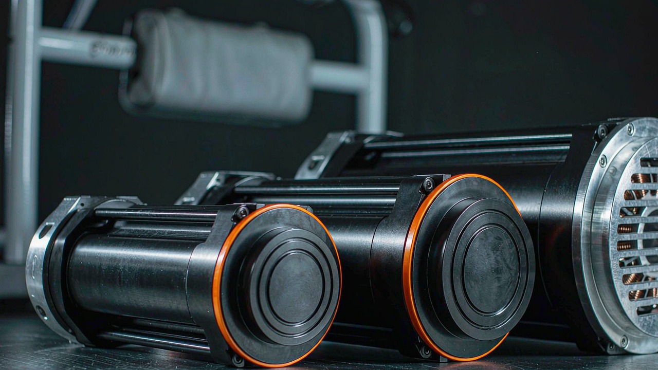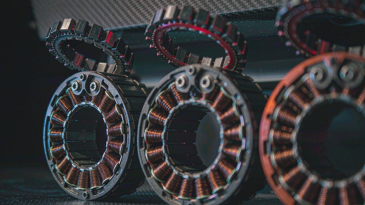
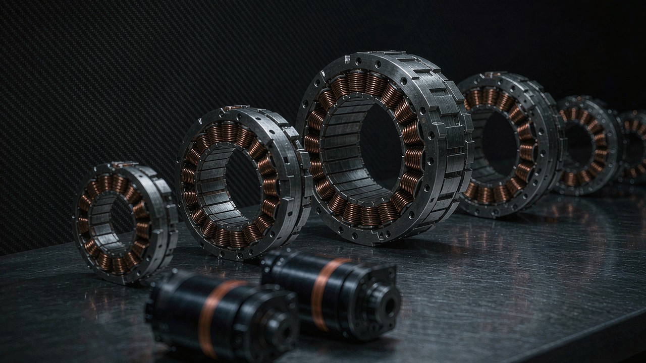
A wheel robot does not need a reducer to get torque at the tyre: it needs a structure that can carry the robot. Every direct-drive unit currently grouped in the Wheel Robot application ships as a bare stator and rotor with no housing and no bearings of its own, so the machine weight that arrives at the hub as a radial load has to be taken by something the builder provides. The two geared modules in the same group publish a rated radial load figure instead - 18 kg on the AKA60-6 KV80 and 50 kg on the AKA10-9 KV60 - and their manufacturer describes both as built for wheeled robots and AGVs, with the larger one specified to withstand lateral and radial impacts in wheeled platforms. That split, between a bare motor whose load path is the machine and a geared unit whose load path is its own output stage, organises everything else that follows: torque at the contact patch, the speed the wheel actually turns at, the current four wheels draw from one pack, and the number of parts that have to be designed and paid for.
Quick Answer
Eleven BLDC motors for wheel robot duty are currently grouped in this application, and they divide into two architectures rather than into a good and a bad one. Nine are frameless direct-drive kits - five outrunner RO units from 60 g to 710 g and four inrunner RI units from 155.9 g to 500 g - which put their torque straight onto the wheel with no intermediate stage, no backlash and no reduction loss, and which leave the hub bearings, the axle and the radial load path entirely to the machine design. Two are geared integrated modules, the AKA60-6 KV80 at 6:1 and the AKA10-9 KV60 at 9:1, which trade a reduction stage and a small backlash figure for published torque at the output and a published radial load rating. Across the eleven, rated torque spans 0.2 N·m to 18 N·m, peak torque reaches 53 N·m, and mass spans 60 g to 1.06 kg, all as published by the manufacturer.
Three consequences follow, and they are the reason the choice is not made on KV. First, on a direct-drive wheel the motor turns far below its rated speed in normal cruise, so the electrical speed ceiling is not what decides the pick; continuous torque against the worst rung of the duty is. Second, on a geared wheel the opposite is true: the output speed is the figure that can become the binding constraint, because the reduction that buys torque also divides the speed. Third, the radial load that a wheel applies is a load the direct-drive kits do not carry themselves, so the decision is split between the motor and the hub structure rather than settled by the motor alone. The sections below work through each of those in turn, then set the eleven out as one specification table and read it by drive layout.
What a Wheel Robot Asks of a BLDC Motor
A wheeled mobile robot is a continuous-duty machine with an interrupted load. The distinction matters because the two most commonly quoted numbers on a specification panel - peak torque and no-load speed - are the two figures a wheel drive spends least of its life using. A leg joint fires its peak torque for a fraction of a second at touchdown; a wheel drive asks for something close to its continuous capability every time the platform climbs a ramp with a full load, and it does so while the motor is inside a wheel that cannot be ventilated the way a joint on an open frame can.
The wheel is the load path: radial load arrives at the hub
On a joint, the motor output is a torque and the reaction is taken by the structure around it. On a wheel, the same torque arrives together with something a joint never sees: the weight of the machine, transferred through the contact patch and the axle as a radial load on whatever carries the wheel. A frameless kit has no bearings, so on the direct-drive route that load reaches a hub the builder has designed, and the manufacturer's own product notes make the same point about the family: these are supplied as separate rotor and stator components, which is what allows the support structure, flanges and bearing arrangement to be tailored to the machine. The geared route publishes the number instead. The AKA60-6 KV80 is rated at 18 kg of radial load and the AKA10-9 KV60 at 50 kg, the latter described as a structural redesign that raises radial load capacity roughly 120 percent over the AK10-9 at the same torque, and as being optimised for the lateral and radial impacts that a wheeled platform generates.
Continuous duty first, peak last
Rated torque is the figure that can be held within the winding's thermal limits, and on a wheel robot it is the working number. Peak torque is a short-window reserve, and the window itself, together with the ambient and mounting assumptions behind it, sits with the manufacturer's documentation rather than in the product record. Reading the eleven by rated torque alone gives a span from 0.2 N·m on the RO40 KV140 Lite to 18 N·m on the AKA10-9 KV60, a factor of ninety, which is a reminder that this application covers everything from a 60 g kick-scooter-scale wheel to a 50 kg radial load industrial platform.
Kerbs, ramps and reversals
A kerb is a torque event and a ramp is a duty event, and they should not be sized with the same number. Climbing a ramp adds a gravity term that stays on the motor for as long as the climb lasts, which is a continuous-duty problem and belongs against rated torque. A kerb arrives as a short obstruction and is closer to a peak event, bounded by how long the wheel is stalled against it. Reversals matter for a different reason: on a differential-drive base a turn is produced by driving the two sides against each other, so the motors spend part of the manoeuvre absorbing energy rather than delivering it, and that returned energy has to go somewhere in the drive electronics.
Four wheels draw from one pack
The current budget is a sum, not a single figure. Four identical wheels at 4 A rated current each draw 16 A continuously before any allowance for the current surge the platform takes when it starts or when a wheel breaks traction, and the AKA60-6 KV80 publishes exactly 4 A rated while the largest direct-drive unit in the group, the RO100 KV55, publishes 20 A. Selecting on torque alone and discovering the arithmetic afterwards is the usual way a pack ends up undersized.
Direct-Drive Frameless or Geared Wheel Actuator
The architecture question comes before the specification question, because it decides which numbers mean anything for a wheel drive motor. A direct-drive wheel is a motor whose rotor turns at wheel speed. A geared wheel is a motor whose rotor turns at wheel speed multiplied by the reduction ratio, with a gear stage in between. Both are in this application, and the eleven split nine to two in favour of direct drive.
Direct drive: wheel speed equals motor speed
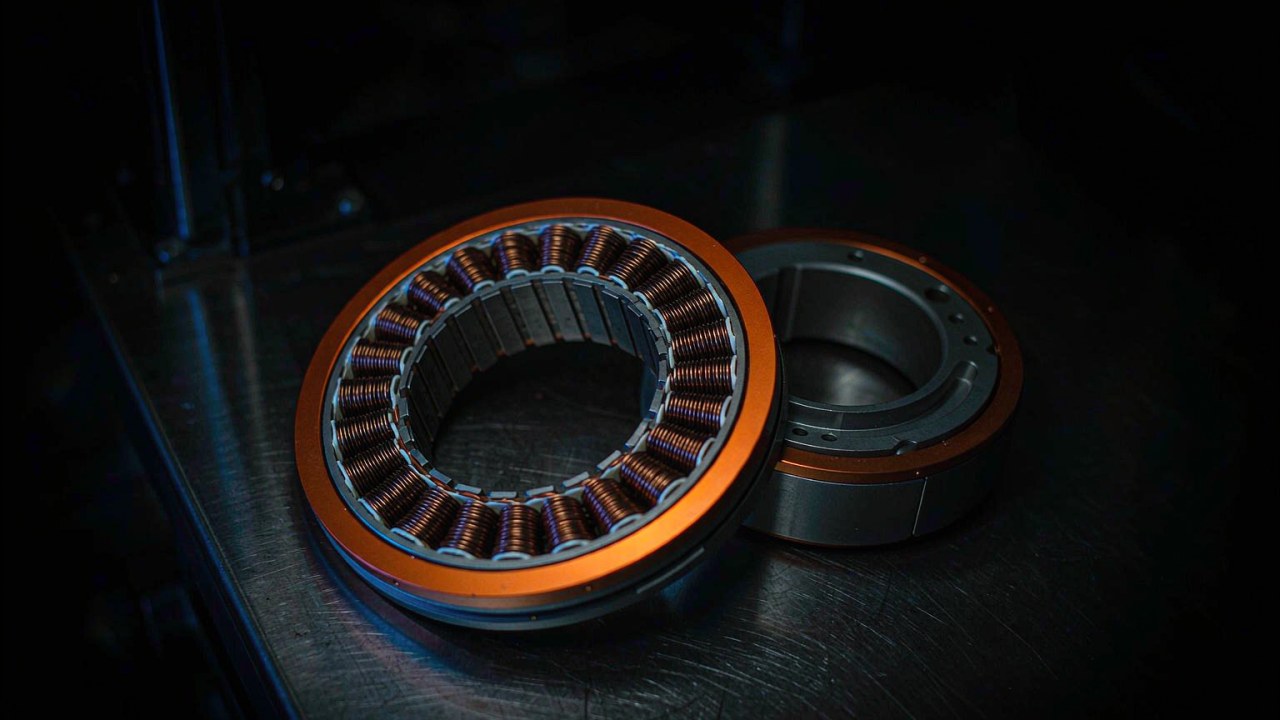
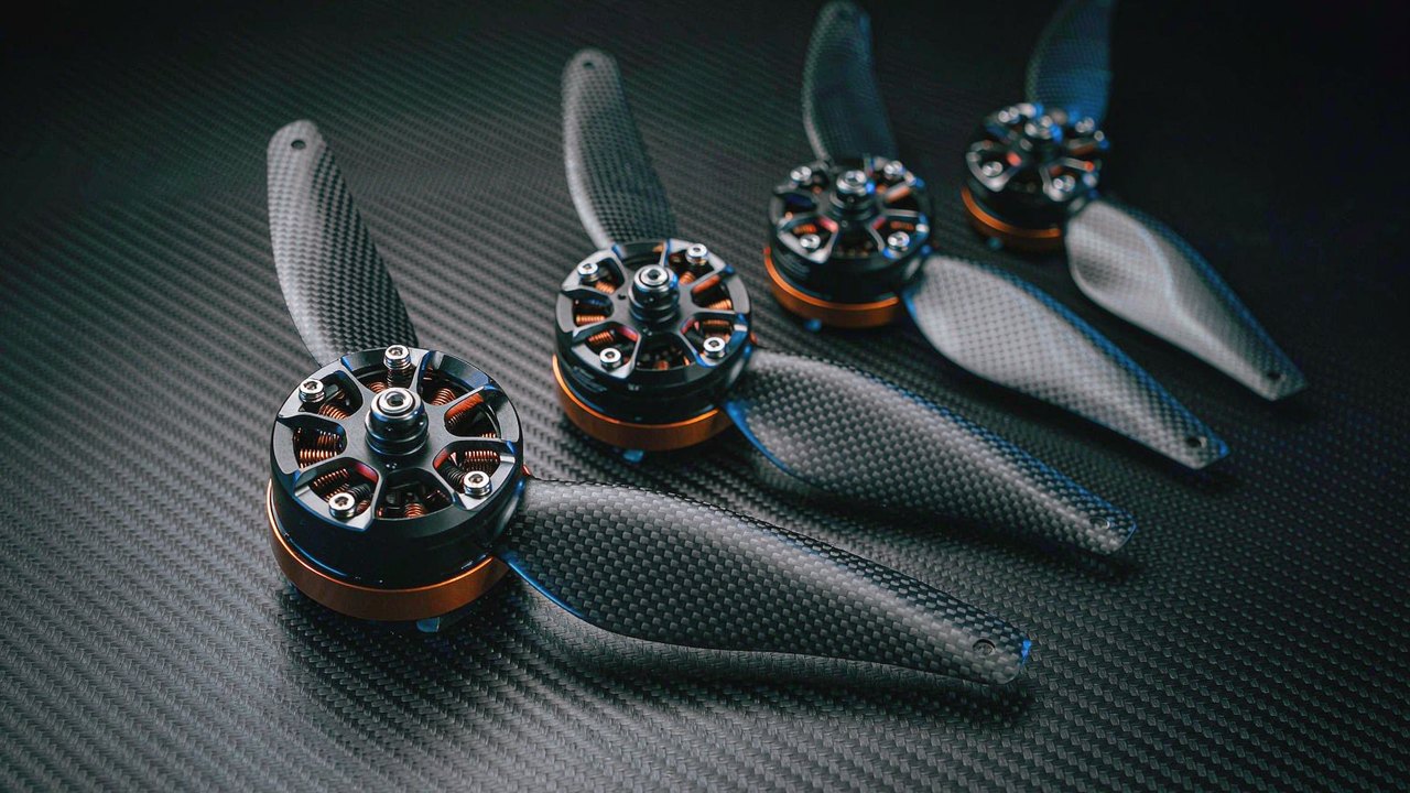
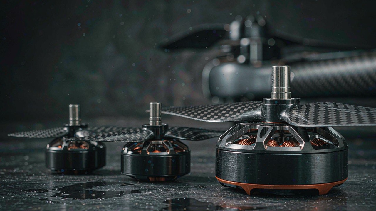
Nine of the eleven - the five RO outrunners and the four RI inrunners - are frameless kits. On a direct-drive wheel the output speed is the motor speed, so the published speed figures can be read against ground speed without any reduction term, and there is no gear stage to contribute backlash, no reduction efficiency to lose, and no additional rotating inertia between the rotor and the tyre. Against that, the torque available at the contact patch is exactly the torque the motor can produce, and the motor must be able to hold the whole wheel duty continuously. The largest direct-drive unit here, the RO100 KV55 Standard, publishes 4 N·m rated and 12 N·m peak at 710 g.
Geared: torque at the tyre, and a stage to account for
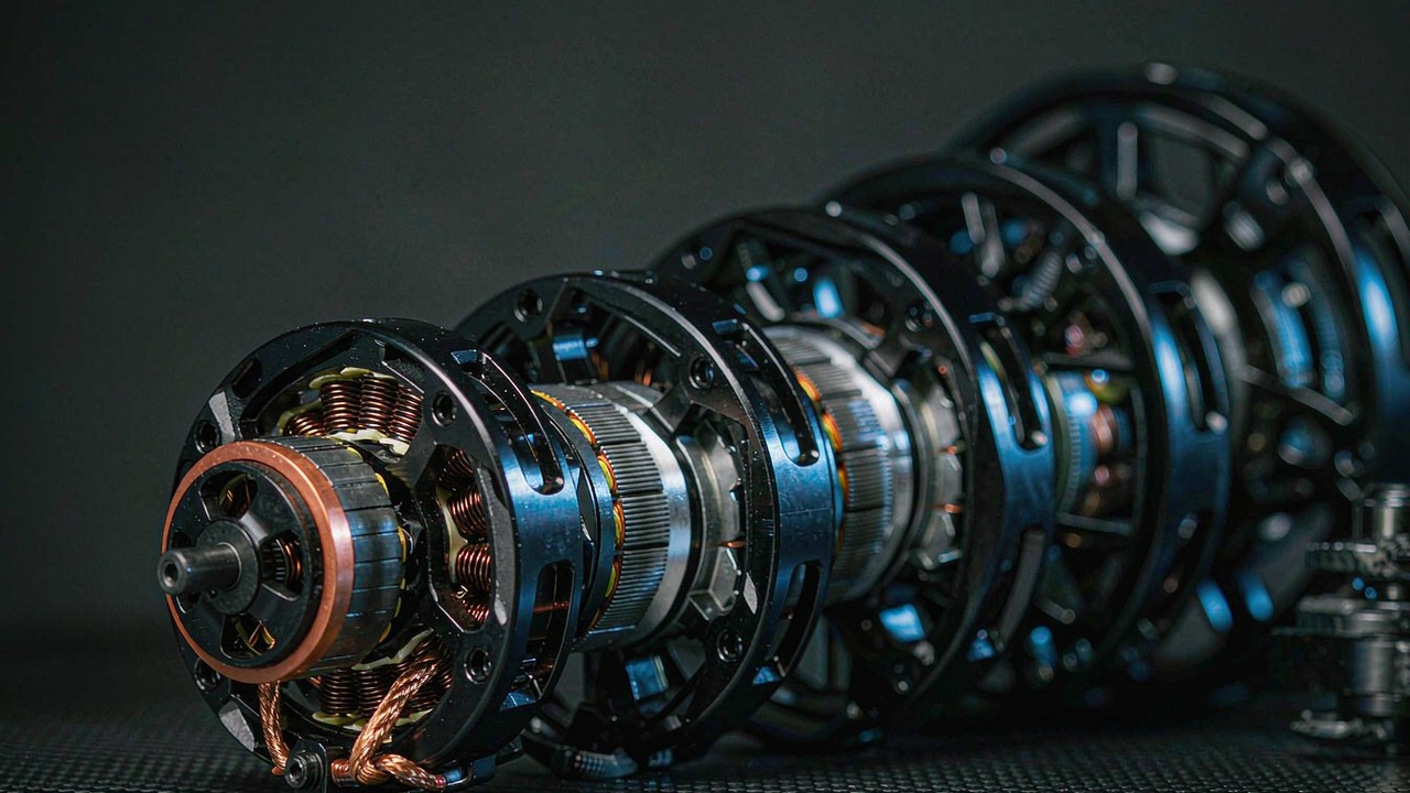
The two AKA modules are the geared option and the only units in the group with a published reduction ratio, a published backlash figure and a published radial load rating. The AKA60-6 KV80 publishes a 6:1 stage, 3 N·m rated and 9 N·m peak at the output, 460 g, and 18 kg of radial load. The AKA10-9 KV60 publishes a 9:1 stage, 18 N·m rated and 53 N·m peak, 1.06 kg, 0.15° of backlash, and 50 kg of radial load, with a single 16-bit magnetic encoder on the output. What the stage buys is torque at the tyre from a lighter motor; what it costs is a speed division, a backlash figure, and the obligation to read every speed value on the output side of the reducer rather than the motor side.
What a frameless kit does not include
A frameless kit is a stator and a rotor. It has no housing, no bearings, no shaft and no encoder unless one is specified, and the manufacturer's notes for the RO family add that the hollow bore is intended for cable routing and for direct coupling to output shafts or a reducer. That is the trade in one sentence: the kit is lighter and mechanically freer than anything housed, and in exchange the bearing arrangement, the housing and the radial load path become part of the machine design. The RI inrunners publish the bore that arrangement is built around - 22 mm on the RI50 KV100, 30 mm on the RI60 KV120, 40.5 mm on the RI80 V2.0 KV75 and 45 mm on the RI100 KV105 - which is the space available for a through axle or a cable run, not a bearing specification.
Backlash belongs to the steer axis, not the drive axis
A wheel that drives and does not steer has no use for a backlash figure in the drive path, because the wheel bears on the ground and the ground is not compliant in the direction of travel. It is a different matter on a swerve or steer module, where a geared unit holds the wheel angle: there, backlash appears as a play in heading before the tyre responds, and it is worth reading as a specification. On the driven-only wheels that make up most of this application the two numbers that matter are the output torque and the radial load rating, and the AKA10-9 KV60 publishes 0.15° of backlash alongside them for the modules that do steer.
Reading Wheel Torque, Speed and Current Off the Published Record
Every figure in the table that follows is the value the manufacturer publishes for that model, and the readings in this section are arithmetic performed on those figures with the wheel diameter stated each time. The purpose is to show which of the published columns actually decides a wheel drive, because two of them turn out to matter much less than their prominence on the specification panel suggests.
From torque at the rotor to thrust at the contact patch
Torque becomes thrust by division by the wheel radius. A 0.58 N·m rated figure - the RI50 KV100 - driving a 125 mm wheel of 0.0625 m radius produces 9.3 N of thrust at the contact patch, and four such wheels produce 37 N collectively. The same arithmetic applied to a 200 mm wheel of 0.1 m radius turns that 0.58 N·m into 5.8 N per wheel, a fall of 37 percent for the same motor, because a larger wheel is a longer lever against the motor. The whole calculation rests on two published columns, rated torque and a stated wheel diameter, and nothing else.
From published speed to ground speed
Ground speed follows from the same wheel by circumference: speed in metres per second equals the wheel circumference in metres multiplied by revolutions per second, or pi times diameter times rpm divided by sixty. At a 125 mm diameter, a cruise of 2 m/s needs 306 rpm at the wheel; at 200 mm the same cruise needs 191 rpm. Those two numbers are the reference against which the published speed columns should be read, and reading them that way produces the single most useful observation in this application. The direct-drive units publish rated speeds between 2000 rpm and 4200 rpm at their published bus levels, which is between six and fourteen times the 306 rpm that a 2 m/s cruise actually requires at a 125 mm wheel. The geared AKA60-6 KV80 publishes 400 rpm at 48 V, or 1.3 times the requirement, and the AKA10-9 KV60 publishes 109 rpm, which is below it, so at a 125 mm wheel diameter that module's rated speed caps ground speed at about 0.71 m/s and only reaches 1.14 m/s if the wheel grows to 200 mm.
Rated current is the number that decides the duty
Current is what heats the winding, and the winding is the surface through which the heat must leave. On a wheel robot the motors sit close to the ground, often inside a wheel or a housing that a machine designer has built for stiffness rather than for airflow, so the thermal path is usually worse than on a joint in open air. Rated current therefore deserves to be read as a duty limit rather than as an electrical detail: the RO100 KV55 Standard publishes 20 A against the RO40 KV140 Lite's 2.85 A, a factor of seven that is a statement about how much heat each winding is expected to shed and over what period.
A triple voltage column in one record
Four of the eleven - the whole RI inrunner group - publish their speed and current values at 24 V, 36 V and 48 V in the same record, on the same winding. That is not a marketing convenience; it is one mechanical specification with three electrical operating points, and for BLDC motors for wheel robot duty it is what allows a platform to be designed around the pack that already exists rather than around a voltage chosen to suit the motor. The table below sets those three columns out side by side.
| Model | Rated Voltage | No-load Speed (24 V) | No-load Speed (36 V) | No-load Speed (48 V) | Rated Speed (24 V) | Rated Speed (36 V) | Rated Speed (48 V) | Rated Torque |
|---|---|---|---|---|---|---|---|---|
| RI60 KV120 | 24/36/48 V | 2532 rpm | 3798 rpm | 5064 rpm | 1440 rpm | 2320 rpm | 3190 rpm | 0.57 Nm |
| RI50 KV100 | 24/36/48 V | 2004 rpm | 3006 rpm | 4008 rpm | 1090 rpm | 1860 rpm | 2600 rpm | 0.58 Nm |
| RI80 V2.0 KV75 | 24/36/48 V | 1480 rpm | 2220 rpm | 2960 rpm | 1135 rpm | 1785 rpm | 2430 rpm | 1.45 Nm |
| RI100 KV105 | 24/36/48 V | 2184 rpm | 3276 rpm | 4368 rpm | 1370 rpm | 2100 rpm | 2825 rpm | 1.76 Nm |
Rated voltage, no-load speed at each published bus level, rated speed at each published bus level, and rated torque, as published by the manufacturer for the four inrunner models currently grouped in the Wheel Robot application. Rated speed is the output-side figure at rated torque; no-load speed is the ceiling at that bus level. In each record the three columns share one rated torque, one peak torque and one rated current, which is what makes them three electrical operating points on a single mechanical specification. The no-load speed columns scale exactly with the bus level, the 36 V figure being 1.5 times the 24 V figure and the 48 V figure twice it in every row; the rated speed columns rise a little faster than that, by between 1.53 and 1.71 times at 36 V and between 2.06 and 2.39 times at 48 V, all four ratios derived by dividing each published column by the 24 V column of the same row and model. Wheel speed and ground speed are not tabulated: turning a published rpm into a ground speed requires a stated wheel diameter, and that calculation appears in the text rather than in the table.
Read down the pairs and the trade is exact. Raising the bus from 24 V to 48 V doubles the no-load speed exactly and raises the rated speed by between 2.06 and 2.39 times, and leaves rated torque, peak torque and rated current untouched, because torque is set by winding current and the winding carries the same current for the same torque at either bus level. What the higher bus adds is the headroom to reach the upper part of the speed column at all, where back-EMF would otherwise limit how much current the drive can deliver. What it does not add is continuous torque, and continuous torque is what a wheel robot spends its life using.
BLDC Motors for Wheel Robot: Spec Comparison Matrix
The eleven models currently grouped in the Wheel Robot application are set out below as one specification set, ordered by published rated torque so that the step from the smallest wheel unit to the load-bearing one is visible in the column itself. Every figure is the value the manufacturer publishes for that model and that this platform holds in its product record. Rated voltage is shown as published, so a triple-rated record appears with all three levels.
| Model | Rated Voltage | Rated Torque | Peak Torque | Rated Current | Rated Speed | Weight | Envelope |
|---|---|---|---|---|---|---|---|
| RO40 KV140 Lite | 24 V | 0.2 Nm | 0.6 Nm | 2.85 A | 2450 rpm | 60 g | Ø46.3 × 13 mm |
| RO50 KV108 Lite | 24 V | 0.3 Nm | 0.9 Nm | 3.4 A | 2100 rpm | 105 g | Ø61.7 × 14.5 mm |
| RI60 KV120 | 24/36/48 V | 0.57 Nm | 1.63 Nm | 5.6 A | 1440/2320/3190 rpm | 155.9 g | Ø60 × 23 mm |
| RI50 KV100 | 24/36/48 V | 0.58 Nm | 1.67 Nm | 4.8 A | 1090/1860/2600 rpm | 180.8 g | Ø54 × 27 mm |
| RO60 KV115 Standard | 48 V | 0.8 Nm | 2.4 Nm | 8.5 A | 4200 rpm | 248 g | Ø73.8 × 23 mm |
| RO80 KV105 Standard | 48 V | 1.3 Nm | 4 Nm | 15 A | 3600 rpm | 352 g | Ø92.6 × 26.4 mm |
| RI80 V2.0 KV75 | 24/36/48 V | 1.45 Nm | 4.1 Nm | 9.4 A | 1135/1785/2430 rpm | 411 g | Ø85 × 27 mm |
| RI100 KV105 | 24/36/48 V | 1.76 Nm | 4.95 Nm | 13.6 A | 1370/2100/2825 rpm | 500 g | Ø104 × 26 mm |
| AKA60-6 KV80 | 24/48 V | 3 Nm | 9 Nm | 4 A | 200/400 rpm | 460 g | Ø80 × 51.2 mm |
| RO100 KV55 Standard | 48 V | 4 Nm | 12 Nm | 20 A | 2000 rpm | 710 g | Ø113.5 × 36.2 mm |
| AKA10-9 KV60 | 48 V | 18 Nm | 53 Nm | 10.6 A | 109 rpm | 1060 g | Ø100 × 70 mm |
Rated voltage, rated torque, peak torque, rated current, rated speed, mass and envelope as published by the manufacturer, for the models currently grouped in the Wheel Robot application, ordered by rated torque. Rated torque is the continuous figure within the winding's thermal limits; peak torque is a short-window figure, and the window, the ambient assumption and the mounting condition behind either torque figure sit with the manufacturer's documentation rather than in the record. A single voltage figure means a single-bus model; a dual or triple figure means the model is published at each of those bus levels, with the corresponding speed figures published separately for each, in the ascending order of the voltage column. Rated speed is the output-side figure at rated torque, so on the two geared modules the figure is already divided by the reduction ratio. Envelope is given as outer diameter by body length and excludes shaft, cable and connector overhang; on the frameless kits it is the stator and rotor assembly, and on the geared modules it is the complete unit including its own bearing arrangement. No reduction ratio column appears: nine of the eleven records carry no reduction stage at all, and the ratios for the two that do are set out in the text.
Two readings stand out once the eleven are on one page. The first is that the torque column and the mass column are not parallel. The RO100 KV55 Standard publishes 4 N·m rated from 710 g, while the AKA60-6 KV80 publishes 3 N·m rated from 460 g, and the AKA10-9 KV60 reaches 18 N·m from 1.06 kg. The geared modules are doing with a stage what the direct-drive units do with copper and magnets, and the price of that is the speed column, which falls from four figures on the direct-drive units to 400 rpm and then 109 rpm.
The second is that rated current does not follow rated torque either. The AKA10-9 KV60 holds 18 N·m from 10.6 A, because the reduction stage converts motor torque into output torque without proportionally increasing motor current, while the RO100 KV55 Standard needs 20 A for 4 N·m. Read as a duty limit, that difference is worth more to a battery-powered platform than the torque figures alone suggest: a geared wheel converts pack current into wheel torque more efficiently, at the cost of a backlash figure and a speed ceiling that has to be checked against the intended cruise speed.
Reading the Eleven by Drive Layout
The table sorts by torque, which is the right order for a selection decision and the wrong order for understanding what the group contains. Read by construction instead, the eleven fall into four blocks: two 24 V outrunner kits, three 48 V outrunner kits, four inrunners, and the two geared modules.
The 24 V Lite pair: RO40 KV140 and RO50 KV108
The two Lite outrunners are the smallest and lightest units in the group and the only ones rated at a single 24 V bus. The RO40 KV140 Lite publishes 0.2 N·m rated and 0.6 N·m peak from 60 g in a Ø46.3 × 13 mm envelope, and the RO50 KV108 Lite publishes 0.3 N·m rated and 0.9 N·m peak from 105 g at Ø61.7 × 14.5 mm. Both are supplied without Hall sensors as part of the Lite specification, and both carry a hollow bore intended for cable routing rather than for a load-bearing shaft. A wheel built around either closes its servo loop on an encoder the machine provides rather than on sensing inside the motor, which is the mechanical consequence of the Lite specification rather than a limitation of the winding.
The 48 V Standard trio: RO60 KV115, RO80 KV105 and RO100 KV55
The three Standard outrunners move to a single 48 V bus and add Hall and temperature sensing as part of the specification. The RO60 KV115 Standard publishes 0.8 N·m rated and 2.4 N·m peak from 248 g, the RO80 KV105 Standard 1.3 N·m rated and 4 N·m peak from 352 g, and the RO100 KV55 Standard 4 N·m rated and 12 N·m peak from 710 g at Ø113.5 mm. Read down the trio, mass rises 2.9 times while rated torque rises 5 times, so the larger units are not simply scaled versions of the smaller ones. The RO100 KV55 Standard also publishes the highest rated current in the group at 20 A, which is the figure that matters once four wheels are driven from one pack.
The four inrunners: RI50 KV100, RI60 KV120, RI80 V2.0 KV75 and RI100 KV105
The RI group is built the other way round: the magnets are on the inside and the winding surrounds them, so the rotor is the inner member and the assembly carries a through bore rather than a hollow shaft. That bore is published on all four records and is the design envelope for a through axle or a cable run - 22 mm on the RI50 KV100, 30 mm on the RI60 KV120, 40.5 mm on the RI80 V2.0 KV75 and 45 mm on the RI100 KV105. All four are published at 24 V, 36 V and 48 V, and all four are rated between 0.57 N·m and 1.76 N·m, which places them in the same torque band as the RO60 and RO80 outrunners while offering a different mechanical interface and a wider bus range.
The two geared wheel actuators: AKA60-6 KV80 and AKA10-9 KV60
In this group, the two AKA modules are the ones whose published records name wheeled robots in their application row. Both records list AGV and wheeled robot as the stated application, while the RO Standard trio names a collaborative robot arm, the four inrunners name a collaborative robot arm or an exoskeleton, and the Lite pair publishes no application row at all. The AKA60-6 KV80 offers a 6:1 stage, 3 N·m rated and 9 N·m peak, 4 A rated current, 460 g and an 18 kg radial load rating, with the manufacturer stating that the reinforced load path raises radial capacity around 52 percent over the AK60-6 at similar torque. The AKA10-9 KV60 offers 9:1, 18 N·m rated and 53 N·m peak, 10.6 A rated current, 1.06 kg, 50 kg of radial load, 0.15° of backlash and a 16-bit magnetic encoder on the output. The 9:1 record is also the one whose rated speed, 109 rpm, has to be checked against the intended cruise speed before anything else about it is considered.
Outrunner or inrunner at the same torque
Where two units in the group publish comparable torque, the choice between them is mechanical rather than electrical. The RO80 KV105 Standard and the RI80 V2.0 KV75 publish 4 N·m and 4.1 N·m of peak torque respectively, from 352 g and 411 g, at Ø92.6 × 26.4 mm and Ø85 × 27 mm. The outrunner is lighter and slightly wider; the inrunner is narrower in diameter, 59 g heavier, and offers a 40.5 mm through bore as well as a 24/36/48 V bus instead of a single 48 V rating. Neither difference is a performance difference, and both are settled by what the wheel structure can accept: an outrunner needs radial clearance around its rotating outer member, an inrunner needs bore space and a shaft through it. The wider treatment of the frameless family as a whole is set out in Frameless Torque Motors: 12 Models Compared, From Entry to Performance Tier.
Mounting, Bearings and the Radial Load Path
This is the part of a wheel robot design that no motor specification settles, and it is the reason the direct-drive route costs engineering time rather than money. It is also where any shortlist of BLDC motors for wheel robot candidates is finally separated, because on this question the published figures bound the problem instead of answering it. The figures do bound it usefully, though: wherever a record carries a rated radial load, that load is carried inside the unit, and wherever it does not, the load is carried by the machine.
What carries the robot's weight
On the two geared modules the answer is stated. The AKA60-6 KV80 is rated at 18 kg of radial load and the AKA10-9 KV60 at 50 kg, and the manufacturer describes the larger one as a structural redesign built to take lateral and radial impacts in wheeled platforms. Those two figures are the published answer to the question every wheel robot asks, and they are what a bearing arrangement inside the module is sized against. On the nine frameless kits no equivalent figure appears, because there is no bearing arrangement to size: the manufacturer's notes for the family describe the kits as separate stator and rotor components supplied so that the support structure, the flange and the bearing arrangement can be designed around the machine.
The bore is a routing decision
The published bore figures are worth reading as design constraints rather than as features. A 45 mm through bore on the RI100 KV105 is enough for a cable bundle or a stationary axle to pass through the centre of the wheel, which is what allows a wheel drive to be built without a rotating cable connection. A 22 mm bore on the RI50 KV100 is enough for a cable run but not for a structural axle at the same scale. The RO outrunners publish their bore as a hollow design intended for the same purpose, and the RO40 and RO50 carry it in a 13 mm and 14.5 mm body length respectively, which is the space available in the smallest wheels in the group.
What the published documentation settles, and what it does not
What is published, for every model in this group, is the electrical and mechanical specification: rated and peak torque, rated current, rated speed at each bus level, mass, envelope, and where applicable the bore, the reduction ratio, the backlash and the rated radial load. What is not published in the product record is the duty window behind peak torque, the ambient and mounting assumptions behind the thermal figures, the bearing life behind a radial load rating, and the sealing arrangement in a wet or dusty environment. Those four items sit with the manufacturer's datasheet and technical drawing, and on a wheeled platform that operates outdoors they are worth resolving before the specification is frozen rather than after.
Selecting BLDC Motors for Wheel Robot: A Sizing Sequence
The order below is the order the figures in this application have to be resolved in, because each step removes candidates that the next step cannot put back.
- Fix the wheel diameter and the cruise speed. These two numbers produce the wheel rpm the duty needs - at 125 mm, 306 rpm for 2 m/s - and that single figure immediately separates the direct-drive wheel drive motor candidates, which have speed to spare, from the geared candidates, whose rated speed may be the binding constraint.
- Fix the continuous duty and the worst-case kerb. Continuous torque against the ramp and the loaded cruise decides which rated torque column is acceptable; the kerb decides how much peak torque has to be available, and for how long, against the manufacturer's stated peak window.
- Fix the bus and the current budget. The bus follows from the pack that already exists, and the four inrunner records publish three bus levels on one winding for exactly that reason. The current budget is the rated current sum across all driven wheels, and it is the figure that decides pack, cabling and drive electronics.
Only after those three steps does the architecture question resolve, and it resolves against the radial load rather than against the torque: where the wheel has to carry the machine through its own output stage, the two geared modules are the group that publishes a rating for it; where the machine will carry the wheel through a hub the design team controls, the nine frameless kits are the group that leaves the room to do so. The integrated module as a category is treated in more depth in Robotic Actuators: How to Choose the Right Integrated Actuator for Robot Joints.
Where Wheel Drive Motors Are Used
The application pages on this platform group machines by what they do rather than by what they contain, and wheel robot duty appears under several of them. The distinctions below are about drive layout, not about size.
Differential-drive AMRs and indoor service robots
A two-wheel differential base with castors is the simplest wheel robot and the one where the direct-drive kits are most often the answer, because the wheel is small, the duty is smooth floor and the radial load is light. The 24 V Lite pair sits at the bottom of that range and the 48 V Standard trio above it. The AGV application covers the same drive architecture where the duty is industrial and continuous.
Outdoor and field wheeled platforms
Outdoor platforms add kerbs, gradients, dust and vibration, and those change the specification in two directions at once: continuous torque rises with the payload and the gradient, and the radial load path matters more because the impacts are larger. This is where a published radial load rating is worth more than a torque figure, and where the geared modules and the larger direct-drive units are the natural shortlist.
Swerve-drive and omnidirectional bases
A swerve module separates the two functions a wheel performs: one motor drives the wheel and another steers it. Steering brings backlash back into the specification, because it appears as play in heading, and it also divides the duty so that the drive motor and the steer motor can be specified separately rather than one unit being oversized for both.
Wheeled-legged and hybrid machines
The hybrid machines that roll on wheels and step over obstacles put the wheel drive and the leg joint in the same vehicle, and the wheel duty there is unusual: long periods of low torque while rolling, punctuated by load transients when the machine steps. That favours a unit with a wide gap between rated and peak torque over one optimised for either extreme, and the wheeled end of that duty is the subject of this page while the legged end is treated in Choosing a BLDC Motor for Quadruped Robot: Torque, Speed and Thermal Limits and in the Quadruped Robot application.
Frequently asked questions
QCan a frameless motor be used directly as a wheel motor?
Yes, provided the machine supplies what the kit does not. A frameless kit is supplied as a separate stator and rotor with no housing, no bearings and no shaft, so the wheel hub, the bearing arrangement and the radial load path become part of the machine design rather than part of the motor. The manufacturer's notes for the family describe the support structure, the flange and the bearing arrangement as items the integrator designs, and the published hollow bore is intended for cable routing and for direct coupling to an output shaft or a reducer.
QWhat separates the RO and RI direct-drive kits for a wheel drive?
Construction, and with it the mechanical interface. The RO units are outrunners with the rotating member outside the winding and are published at either a single 24 V bus, in the Lite pair, or a single 48 V bus, in the Standard trio. The RI units are inrunners with the rotor inside the winding, are published at 24 V, 36 V and 48 V on one winding, and publish a through bore that the RO records express as a hollow design. The RO80 KV105 Standard and the RI80 V2.0 KV75 are the closest pair on torque, at 4 N·m and 4.1 N·m of peak torque, which makes them the cleanest comparison of the two constructions.
QHow much torque can a direct-drive wheel motor hold continuously?
Across the nine direct-drive kits currently grouped in this application, rated torque runs from 0.2 N·m to 4 N·m. That figure is the one to compare against the gradient and the loaded cruise, because it is the value the winding can hold within its thermal limits. Torque at the contact patch is the rated torque divided by the wheel radius: 0.58 N·m on a 125 mm wheel produces 9.3 N of thrust, and on a 200 mm wheel the same motor produces 5.8 N, so the wheel diameter belongs in the calculation rather than being assumed.
QWhen is a geared wheel actuator the right answer?
When the duty needs more torque at the tyre than a direct-drive winding can hold continuously, or when the wheel has to carry the machine through the unit's own output stage. The two geared modules here publish 3 N·m rated and 9 N·m peak at 6:1, and 18 N·m rated and 53 N·m peak at 9:1, together with rated radial loads of 18 kg and 50 kg. The trade is visible in the same records: the 9:1 unit's rated speed is 109 rpm, which at a 125 mm wheel caps ground speed at about 0.71 m/s, so the cruise speed has to be checked before the torque advantage is taken.
QWhy does one motor publish three speed figures?
Because it is one mechanical specification published at three electrical operating points. The four inrunner records list a rated voltage of 24/36/48 V and give a no-load speed and a rated speed for each level, while rated torque, peak torque and rated current stay the same across the three. The no-load speed columns scale exactly with the bus, the 36 V figure being 1.5 times the 24 V figure and the 48 V figure twice it, while the rated speed columns rise by between 1.53 and 1.71 times at 36 V and between 2.06 and 2.39 times at 48 V. Reading a wheel speed off the wrong column, or forgetting which bus level a single figure belongs to, is the most common way to size a wheel drive against the wrong number.
QShould a wheel drive be sized on peak torque or rated torque?
On both, for different events. Rated torque is the continuous figure and it is what the ramp, the loaded cruise and the long duty have to fit inside. Peak torque is a short-window reserve and it is what the kerb and the start-up surge draw on. The window itself - how long peak torque can be held, at what ambient and in what mounting condition - sits with the manufacturer's documentation rather than in the product record, and on a wheel drive buried inside a wheel housing the mounting condition is usually the least favourable one in the machine.
Official resources
CubeMars publishes an official product page for each unit with its specification panel, technical drawing and control documentation, and those pages remain the source of truth for every figure quoted here - for example the RI50 KV100 product page, the RO100 KV55 Standard product page and the AKA10-9 KV60 product page. The torque, current, speed, mass, envelope, bore, reduction ratio, backlash and radial load figures in the tables above are the values those pages publish, and a duty window, a thermal assumption or a bearing life that a wheel design depends on is a question for the manufacturer rather than a figure that can be inferred from the specification panel.
Where to go next
For shortlisting rather than reading, three tools on the platform do the work in sequence. Explore the full Frameless Torque Motors category to see the nine direct-drive kits and their specifications side by side, use Select to narrow by torque, voltage and mass, then place candidates against each other in Compare Products. Where the wheel has to carry the machine through its own output stage, the Robotic Actuators category holds the geared modules and the rest of the integrated family.
Two further articles carry the parts of this subject that a wheel drive does not settle. Frameless Torque Motors: 12 Models Compared, From Entry to Performance Tier sets the whole frameless family out by band and is the right companion when the drive architecture is settled but the size is not. Choosing a BLDC Motor for Quadruped Robot: Torque, Speed and Thermal Limits covers the legged end of the same duty for machines that both roll and step.
The short version: fix the wheel diameter and the cruise speed first, because they turn a motor speed into a ground speed and expose whether the geared route has the speed to reach it at all; fix the continuous duty and the worst-case kerb second, because rated torque and peak torque answer different events; fix the bus and the current budget last, because the bus follows the pack and the current budget is a sum across every driven wheel. Then decide the architecture against the radial load, which is the one figure the direct-drive kits leave to the machine and the geared modules publish as a rating.