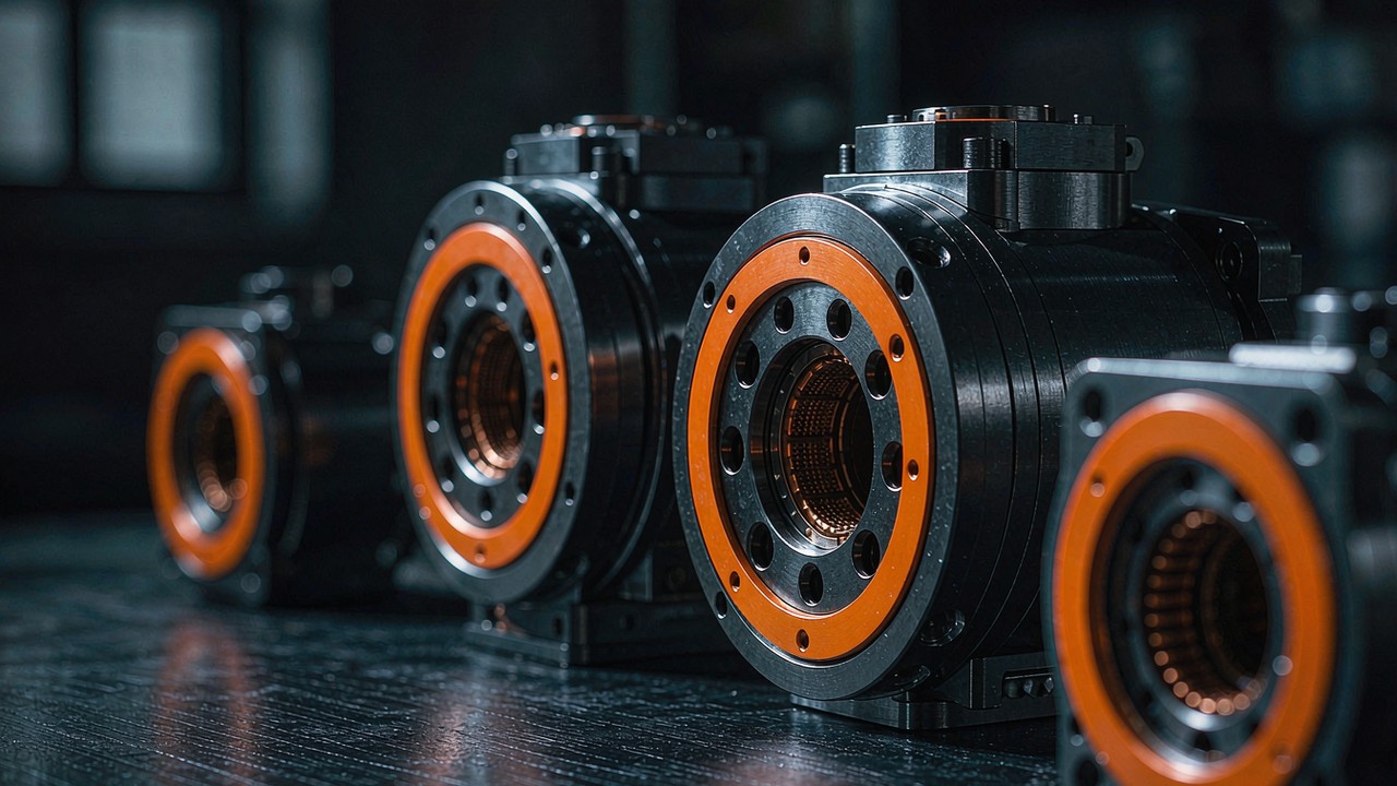
A 48 V bus does not make a robotic actuator stronger. Among the CubeMars modules held in this platform, every record that publishes both a 24 V and a 48 V rating lists the same rated torque and the same rated current for both, and splits only in the speed column, where the 48 V figure is roughly twice the 24 V one. That single pattern reorganises the whole subject. A 48 V bus is a machine-level electrical decision, what it buys is speed and bus-current headroom rather than torque, and the constraints that decide whether it can be used at all sit outside the actuator, in the driver, the battery pack and the harness. Sixteen of the twenty-one integrated actuators currently listed across the Robotic Actuators and Quasi Direct Drive Actuators categories accept a 48 V bus, and the five records that do not are confined to 24 V. This guide covers which models are compatible, what the higher bus changes in a joint, where the benefit stops, and how the surrounding system has to be designed around it.
Quick Answer
Sixteen of the twenty-one integrated actuators currently listed on this platform accept a 48 V bus, spread across two product categories. In the CubeMars records, running a dual-rated module at 48 V raises the speed ceiling to roughly twice the 24 V figure and leaves rated torque, peak torque and rated current unchanged, because torque is set by winding current and the winding carries the same current for the same torque either way. What a higher bus also buys is headroom at the top of the speed range, where back-EMF would otherwise limit how much current the driver can deliver. What it does not buy is continuous torque, since that figure is bounded by the winding's thermal path and by the duty cycle. The constraints are system-level rather than module-level: the driver's own input window, the way returned energy is absorbed during deceleration, insulation and connector practice, and the pack, charger and battery management arrangement feeding the bus. The sections below follow that order: what changes inside the actuator, what the change is worth, what it costs to accommodate, which models are affected, and how to match one to a joint.
What 48 V Actually Changes Inside a Robotic Actuator
The bus is not a property of the actuator. It is a property of the machine, and the module is one of its loads. Reading a 48 V robotic actuator record correctly means separating the two columns a manufacturer publishes when a model supports more than one bus, and being precise about which figures move when the bus moves. For an integrated module that combines motor, reduction stage, driver and feedback, the split is narrower than it first appears.
The bus is chosen outside the module
A robotic actuator sees a DC bus and a control interface. Nothing about the reduction ratio, the bearing arrangement, the envelope or the mounting pattern depends on whether that bus sits at 48 V or at a lower level. What the bus sets is the voltage available to the driver, and through the driver it sets the speed at which a given current can still be driven into the winding. The choice therefore belongs with the machine architect, alongside pack topology, charger selection and the thermal budget of the enclosure the module will sit in. An actuator datasheet that publishes two bus ratings is not offering two products; it is reporting one product at two operating points.
One bus, two published ratings: what a 24/48 V record means
Five of the integrated actuators currently listed here carry a dual bus rating rather than a single one: AK10-9 V2.0 KV60, AK60-6 V3.0 KV80, AK70-10 KV100, AK80-64 KV80 and AKA60-6 KV80. Their records publish two rated speeds and two no-load speeds, separated by a slash, and in each case the pair is the 24 V figure followed by the 48 V figure. The same records publish a single rated torque, a single rated current and a single peak torque. That asymmetry is the whole story in one line of a specification table: the electrical work the module does is a function of current, and the current required for a given torque does not change with the bus.
Dual rating is not simply a matter of age or version. AK10-9 V3.0 KV60, the later revision, publishes a single 48 V rating, while the earlier AK10-9 V2.0 KV60 carries both. The later revision also publishes a higher peak torque, 53 Nm against 48 Nm, on a slightly lower mass. Bus support and mechanical revision have to be read from the record rather than inferred from the model number.
Torque and current stay put while the speed column splits
The published pairs are consistent enough to state the effect as a rule rather than an impression. AK10-9 V2.0 KV60 is rated at 109 rpm on 24 V and 228 rpm on 48 V, with no-load speeds of 160 rpm and 320 rpm. AK70-10 KV100 moves from 148 rpm to 310 rpm rated, and from 240 rpm to 480 rpm no-load. AK80-64 KV80, the 64:1 unit, moves from 23 rpm to 48 rpm rated and 37 rpm to 75 rpm no-load. AKA60-6 KV80 doubles from 200 rpm to 400 rpm rated and from 320 rpm to 640 rpm no-load, and AK60-6 V3.0 KV80 from 233 rpm to 490 rpm and from 320 rpm to 640 rpm. Across all five, the 48 V figure sits between about two and about two-and-a-tenth times the 24 V figure at both the rated and the no-load point.
Against that, none of the five changes its rated torque, its peak torque or its rated current between the two columns. AK60-6 V3.0 KV80 is rated at 3 Nm and 3.8 A on both buses and peaks at 9 Nm on both; the peak current pair is 10.3 A and 11.2 A, close enough that the small difference is more likely a measurement or rounding convention than a different winding limit. The practical consequence is that the winding loses the same heat at a given torque on either bus, the copper loss per newton metre is unchanged, and the thermal limit on continuous torque is therefore identical. Anyone expecting a 48 V bus to unlock more continuous torque out of the same module is reading the wrong column.
What does not move: the reduction ratio and the envelope
Bus voltage also leaves the mechanical record untouched. A 48 V robotic actuator has the same reduction ratio, the same backlash class, the same outer diameter, the same stack length and the same mass as the same module run at a lower bus, because none of those quantities is electrically referenced. AK80-8 KV60 stays at 8:1 and 98 mm by 43.9 mm on either side of the bus decision. AKH70-48 V1.0 KV41 stays at 48:1 inside a 90 mm diameter body 81.5 mm long. This matters for design sequence: the envelope and the ratio can be fixed before the pack topology is settled, and a later move from 24 V to 48 V does not reopen the mechanical design.
Performance Benefits of Running Robotic Actuators on a 48 V Bus
The benefit of a higher bus is often described as efficiency, and that framing obscures where the gain actually appears. In an integrated module the winding current is set by the torque the joint is asked to produce, and the reduction stage and the driver sit between that winding and the bus. What the bus controls is the speed at which the required current can still be pushed, and how much current has to travel through the machine's own wiring to deliver a given mechanical power.
The speed ceiling scales with the bus at the same KV
Speed at the motor is set by the winding's velocity constant and the voltage available to drive current into it. Doubling the bus while keeping the winding raises the no-load ceiling, and the reduction stage divides that ceiling down to the joint. This is visible directly in the published pairs rather than through any calculation: AK10-9 V2.0 KV60 goes from 160 rpm to 320 rpm no-load, AK70-10 KV100 from 240 rpm to 480 rpm, AKA60-6 KV80 from 320 rpm to 640 rpm. At the joint, a module with a fixed ratio therefore sees its available speed double. For a joint whose duty is dominated by tracking speed rather than by holding torque, that is the difference between a module that fits the brief and one that does not. It is also the reason a dual-rated module can be specified for a platform that is expected to move from a lower-voltage prototype pack to a 48 V production pack without changing the actuation.
The same current carries more power
Mechanical power is the product of torque and speed. If a module holds a given current, and therefore a given torque, to a higher speed, the mechanical power available from that same current rises in proportion. That is the honest form of the efficiency argument: it is not that the winding becomes more efficient at 48 V, it is that the same thermal budget, expressed as current in the winding, is converted into more output power because the operating point can be pushed further up the speed axis before the driver runs out of voltage. Where a joint needs both torque and speed rather than one or the other, the higher bus lifts the ceiling on the product of the two.
Where the current saving appears: the harness and the pack
The saving is real, but it appears at the machine level rather than inside the module. For a given mechanical power, a bus at twice the voltage draws about half the current, and bus current is what sizes cables, connectors and the protection around them. On a machine with several actuators fed from a common bus, that reduction propagates through the shared harness, the distribution board and the pack's own discharge path. It matters most where links are long or where many joints are supplied from a single bus, and least on a short, single-joint bench build. It also changes the shape of the pack: the same energy is delivered with less current per cell group, which spreads the load across a series string rather than concentrating it.
Headroom for the peak window at the top of the speed range
Peak torque is a short-window figure, and reaching it at speed requires the driver to overcome the back-EMF the spinning motor generates before any current can flow. A higher bus leaves more voltage for that, so the peak torque window stays reachable further up the speed range. This is a distinct benefit from the no-load speed ceiling and it is often the practical reason a machine moves to a higher bus: the joint does not need to spin faster in steady state, but it needs to deliver a short burst of torque while already moving quickly. A dual-rated module reports the same peak torque on both buses, and the higher bus is what makes that figure attainable at the upper end of the speed range rather than only near stall.
What the higher bus does not buy
A 48 V bus does not raise rated torque, does not change the reduction ratio, does not reduce the heat generated at a given output torque, and does not change the backlash class or the bearing rating. Neither does it change the module's published operating ambient temperature range, which is the same statement across the family. On a duty that is dominated by holding torque against gravity at low speed, the module sees no benefit at all from the higher bus, and the additional voltage regulation, protection and insulation work is cost without return. The bus decision should be made on the shape of the speed-torque duty, not on the assumption that more volts is a general improvement.
System Constraints That Decide Whether 48 V Is Usable
Because the bus belongs to the machine, the constraints on using it are mostly machine constraints. Some of them are published on the product records and can be read directly; others depend on the driver's own documentation and on the pack design, and have to be confirmed at system level. The list below separates the two.
The driver's input voltage window
The module's driver is the component that sees the bus, so the permissible input window of that driver is the first gate. The product records state that the modules carry built-in protection against overcurrent, overvoltage and undervoltage, and against overtemperature, which means the driver is monitoring the bus it sits on rather than accepting any voltage within a wide range. The rated voltage figure in the specification is an operating point, not a permissible maximum. Where a design intent is to run a module at the top of a charging cycle, or where the pack can be charged while the machine is powered, the permissible input window and the protection thresholds for that specific module and firmware should be confirmed against the manufacturer's current documentation before the pack is specified.
Regeneration, bus transients and where the returned energy goes
Any joint that decelerates a load backdrives its motor, and a backdriven motor becomes a generator that returns energy to the bus rather than drawing from it. On a bus fed only by a battery, that energy has somewhere to go. On a bench supply, or on a bus with a long cable run and limited capacitance, the returned energy can push the bus above its steady level for the duration of the deceleration, and the transient becomes a system design problem rather than a module problem: capacitance sizing, braking arrangements and the response of the supply all enter the calculation. The relevant figure is not the rated bus voltage but the energy that a specific deceleration profile returns, which depends on the load inertia, the joint speed and the duty cycle. That profile has to be derived from the machine, not read from the actuator record.
Insulation, connectors and the 60 V DC line
Electrical safety frameworks commonly treat a nominal 48 V DC bus as falling within the range handled as safety extra-low voltage, below the 60 V DC threshold that appears in a number of national and international standards, which is one reason the voltage is popular for mobile machines. The applicable standard and its local implementation remain the governing documents, and the threshold applies to the actual maximum bus voltage rather than to the nominal figure. Thermal and current ratings at the module's own interfaces are separate questions, and the connector and wiring practice specified for a machine should follow what the module manufacturer publishes for that interface rather than a general assumption about the voltage class.
Pack, charger and BMS consequences
A nominal 48 V bus is normally built from a series string of lithium-ion cells, and the string's full-charge voltage sits above the nominal figure, which is a property of cell chemistry rather than a specification of any actuator. Two consequences follow. First, everything downstream has to tolerate the top of the charge range and not only the nominal level. Second, the pack's battery management system, its charge profile and its discharge cut-off all define what the actuator actually sees, including during the brief excursions a decelerating joint produces. Where an actuator's permissible window and a pack's operating range are published in different documents, the intersection is the design window, and it is worth writing that intersection down rather than assuming the nominal figures line up.
Thermal behaviour and duty cycle
The thermal limit on continuous torque belongs to the winding and to the path heat takes out of it, and it does not move with the bus. A joint that was thermally marginal at the lower bus remains thermally marginal at 48 V, because the current and therefore the copper loss at a given torque are unchanged. What the higher bus changes is the split between copper loss and the mechanical output available from it. On a duty with long holding phases at low speed, or with a high proportion of time near rated torque, the thermal design is the binding constraint and the bus decision is secondary. On a duty dominated by fast, lightly loaded motion, the speed ceiling is binding instead, and the bus decision is primary.
The questions the published documentation leaves open
Not every number needed to close a system design appears on a product page. The permissible input window and the protection thresholds of the driver, the behaviour of the module under a specific deceleration profile, the torque derating that applies when the module runs at the top of its speed range for an extended period, and the duty-specific continuous torque are all system questions rather than values published on a product page. They are answerable, and the manufacturer's control documentation and application support are the right source, but they should be confirmed before the pack and the harness are frozen. Treating the rated voltage figure as the permissible bus and the peak torque figure as an available torque is the most common way a 48 V design is mis-sized.
48 V Robotic Actuators: Spec Comparison Matrix
The table below reads every 48 V robotic actuator currently listed in the Robotic Actuators category as one specification set, ordered by published rated torque so that the transition from the light joints to the load-bearing ones is visible in the column itself. Every figure is the value the manufacturer publishes for that model and that this platform holds in its product records. Rated voltage is shown as published, so a dual-rated record appears with both levels.
| Model | Rated Voltage | Rated Torque | Peak Torque | Reduction Ratio | Weight | Envelope |
|---|---|---|---|---|---|---|
| AK60-6 V3.0 KV80 | 24/48 V | 3 Nm | 9 Nm | 6:1 | 380 g | Ø79 × 43 mm |
| AKA60-6 KV80 | 24/48 V | 3 Nm | 9 Nm | 6:1 | 460 g | Ø80 × 51.2 mm |
| AK80-6 KV100 | 48 V | 6 Nm | 12 Nm | 6:1 | 485 g | Ø98 × 38.5 mm |
| AK70-10 KV100 | 24/48 V | 8.3 Nm | 24.8 Nm | 10:1 | 621 g | Ø89 × 50.25 mm |
| AK70-9 V3.0 KV60 | 48 V | 8.5 Nm | 29.2 Nm | 9:1 | 540 g | Ø89 × 49 mm |
| AK80-9 V3.0 KV100 | 48 V | 9 Nm | 22 Nm | 9:1 | 490 g | Ø98 × 38.5 mm |
| AK80-8 KV60 | 48 V | 10 Nm | 25 Nm | 8:1 | 570 g | Ø98 × 43.9 mm |
| AK10-9 V2.0 KV60 | 24/48 V | 18 Nm | 48 Nm | 9:1 | 960 g | Ø98 × 61.7 mm |
| AK10-9 V3.0 KV60 | 48 V | 18 Nm | 53 Nm | 9:1 | 940 g | Ø98 × 61.7 mm |
| AKA10-9 KV60 | 48 V | 18 Nm | 53 Nm | 9:1 | 1060 g | Ø100 × 70 mm |
| AK60-39 V3.0 KV80 | 48 V | 24 Nm | 72 Nm | 39:1 | 750 g | Ø79 × 67 mm |
| AK80-64 KV80 | 24/48 V | 48 Nm | 120 Nm | 64:1 | 850 g | Ø98 × 61.9 mm |
| AKH70-16 V1.0 KV41 | 48 V | 26 Nm | 78 Nm | 16:1 | 879 g | Ø90 × 60.5 mm |
| AKH70-48 V1.0 KV41 | 48 V | 74 Nm | 222 Nm | 48:1 | 1396 g | Ø90 × 81.5 mm |
Rated voltage, rated torque, peak torque, reduction ratio, mass and envelope as published by the manufacturer, for the models currently listed in the Robotic Actuators category that accept a 48 V bus, ordered by rated torque. Rated torque is the continuous figure within the winding's thermal limits; peak torque is a short-window figure. A single voltage figure means a single-bus module; a dual figure means the module is published at both levels, with the corresponding speed and power figures also published separately for each. Envelope is given as outer diameter by body length and excludes shaft, cable and connector overhang.
Two things stand out when the matrix is read down the torque column rather than across the voltage column. The first is that the modules reaching 48 V are not a distinct product family: they run from a 3 Nm unit in a 79 mm body to a 74 Nm unit at 1396 g, and the two 6:1 modules sit at the bottom of the table while a 24:1 torque step appears between the 24 Nm record and the 48 Nm one. The second is that bus support is nearly universal in this category. Of the eighteen records currently listed, fourteen accept 48 V; the four that do not are all at the light end of the range, and each is published at a single 24 V rating. A machine built around 48 V therefore has a wide choice of joint sizes from one manufacturer rather than a narrow shortlist.
Reading the table as a shortlist also shows why voltage alone is a poor filter. AK60-6 V3.0 KV80 and AKA60-6 KV80 publish the same rated and peak torque, the same ratio and the same bus support, and differ mainly in packaging: the AKA unit is 80 g heavier and 8.2 mm longer, in a slightly smaller diameter. AK10-9 V3.0 KV60 and AKA10-9 KV60 publish identical torque and ratio figures as well, and differ by 120 g of mass. Those choices are about structure and integration, not about the bus, and they should be made on the mechanical brief.
Reading the Sixteen by Duty, Not by Voltage
Because bus support is close to universal across the category, the useful way to narrow the list is by the duty each module suits. The groups below follow published torque and ratio rather than voltage, since those two figures are what a joint requirement is written against.
The 6:1 pair: AKA60-6 KV80 and AK60-6 V3.0 KV80
Both modules publish 3 Nm rated and 9 Nm peak at a 6:1 ratio, and both accept 48 V. The low ratio makes them the fastest joints in the 48 V group relative to their output torque: AK60-6 V3.0 KV80 publishes 320 rpm no-load on 24 V and 640 rpm on 48 V, and AKA60-6 KV80 publishes the same pair. On a 48 V bus either unit reaches a joint-side speed that no higher-ratio module in the table approaches. The difference between them is packaging and mass: AK60-6 V3.0 KV80 is the lighter of the two at 380 g in a 79 mm by 43 mm body, while AKA60-6 KV80 is 460 g in a 80 mm by 51.2 mm body. Both are suited to a distal axis that has to move quickly under light load, and neither is suited to an axis that has to hold a large static torque.
The 8:1, 9:1 and 10:1 middle of the range
Four modules occupy this band at 48 V, and the spread is wider than the ratio figures suggest. AK80-9 V3.0 KV100 publishes 9 Nm rated and 22 Nm peak at 9:1 in a 490 g, 98 mm by 38.5 mm body. AK80-8 KV60 publishes 10 Nm and 25 Nm at 8:1 in 570 g in a 98 mm by 43.9 mm body. AK70-10 KV100 publishes 8.3 Nm and 24.8 Nm at 10:1 in a 621 g, 89 mm by 50.25 mm body, and AK70-9 V3.0 KV60 publishes 8.5 Nm and 29.2 Nm at 9:1 in 540 g. Ratios this close are a fine-tuning range rather than a set of distinct operating regimes, and the choice within the band usually turns on envelope, on mass, and on how much speed the joint needs at the top of its range. AK70-9 V3.0 KV60 is the one to watch where peak torque matters more than continuous torque, since its 29.2 Nm peak is the highest in the band on the lowest mass of the four.
The heavy joints: AK60-39 V3.0 KV80, AK80-64 KV80, AKA10-9 KV60 and AK10-9 V3.0 KV60
Above 18 Nm rated the table splits into two approaches. AK10-9 V3.0 KV60 and AKA10-9 KV60 both take the high-ratio route at 9:1 and publish 18 Nm rated with a 53 Nm peak, in 940 g and 1060 g respectively; the higher bus is what makes the 9:1 ratio usable at a joint-side speed, since the 48 V no-load figure of 320 rpm is what a 9:1 module can offer. AK60-39 V3.0 KV80 and AK80-64 KV80 take the other route, trading speed for torque through the reduction stage: 39:1 gives 24 Nm rated and 72 Nm peak in 750 g, and 64:1 gives 48 Nm rated and 120 Nm peak in 850 g at a no-load speed of 37 rpm on 24 V and 75 rpm on 48 V. Where a joint has to hold a load against gravity for long periods, that torque per unit of current, bought with the ratio rather than with the bus, is the mechanism at work.
Hollow shaft: AKH70-16 V1.0 KV41 and AKH70-48 V1.0 KV41
The two hollow-shaft modules are distinguished by their reduction ratios rather than by their bus, and the model numbers invite a misreading worth clearing up. The "48" in AKH70-48 V1.0 KV41 is a 48:1 reduction ratio, not a 48 V rating; the same module is published at 48 V, and so is AKH70-16 V1.0 KV41 at 16:1. Both run on the same 41 KV winding. AKH70-16 V1.0 KV41 publishes 26 Nm rated and 78 Nm peak in 879 g, and AKH70-48 V1.0 KV41 publishes 74 Nm and 222 Nm in 1396 g at 81.5 mm of body length. What makes the pair distinctive is the bore: the hollow shaft carries cables through the joint, which changes the harness architecture of a multi-joint limb rather than the joint's torque. The 48:1 unit is the highest-torque 48 V module currently listed here, and the 16:1 unit is the middle step for a joint that needs the bore without the very low output speed that comes with a 48:1 ratio.
The two quasi direct drive modules: AKE80-8 KV30 and AKE90-8 KV35
The other category that contributes 48 V modules to this comparison is Quasi Direct Drive Actuators, and its two 48 V members behave differently from the AK series in a way that matters for system design. AKE80-8 KV30 publishes 12 Nm rated and 30 Nm peak at 8:1 in 570 g in an 87 mm by 32 mm body, and AKE90-8 KV35 publishes 55 Nm rated and 170 Nm peak at 8:1 in 1400 g in a 107.5 mm by 43.5 mm body. Both are built around an 8:1 ratio, which is the defining characteristic of the family and the reason the group is treated separately: the low ratio keeps the joint responsive and back-drivable, and the torque comes from the motor rather than from a deep reduction stage. The third member of the family, AKE60-8 KV80, is published at 24 V only, which is why it does not appear in the 48 V comparison despite sitting in the same category.
The system design point is that the manufacturer's comparison table lists the AKE modules without a driver board, while the AK and AKH modules are listed with one, and the accessory pack for AKE80-8 KV30 contains a separate sensing magnet rather than drive electronics. That is a system-level difference rather than a difference in capability: the module still publishes a FOC drive method and the same bolt-on integration, but the drive and its voltage window sit outside the module in the machine's own electronics, so the input window, the protection arrangement and the harness all have to be specified by the integrator. Where the AK series arrives with its driver inside the envelope, the AKE series moves that decision into the machine. The arrangement for a specific module, including the feedback electronics it expects, should be confirmed against the manufacturer's current documentation before the electrical architecture is frozen.
Designing one joint for both 24 V and 48 V
The five dual-rated modules make a specific engineering option available, and it is worth stating precisely. A machine can be specified around a module whose winding is published at both levels, then run at the lower bus during prototyping and at the higher bus in production, with the same reduction ratio, the same envelope, the same mass and the same rated torque throughout. Only the speed ceiling and the power available at a given current change. The table below sets out the published speed pairs for those five, which is the change in full.
| Model | Rated Voltage | Rated Speed (24 V) | Rated Speed (48 V) | No-load Speed (24 V) | No-load Speed (48 V) | Reduction Ratio |
|---|---|---|---|---|---|---|
| AK10-9 V2.0 KV60 | 24/48 V | 109 rpm | 228 rpm | 160 rpm | 320 rpm | 9:1 |
| AK60-6 V3.0 KV80 | 24/48 V | 233 rpm | 490 rpm | 320 rpm | 640 rpm | 6:1 |
| AK70-10 KV100 | 24/48 V | 148 rpm | 310 rpm | 240 rpm | 480 rpm | 10:1 |
| AK80-64 KV80 | 24/48 V | 23 rpm | 48 rpm | 37 rpm | 75 rpm | 64:1 |
| AKA60-6 KV80 | 24/48 V | 200 rpm | 400 rpm | 320 rpm | 640 rpm | 6:1 |
Rated speed, no-load speed and reduction ratio as published by the manufacturer for the dual-rated modules currently listed in the Robotic Actuators category, with the 24 V and 48 V figures shown in separate columns. Rated speed is the output-side figure at rated torque; no-load speed is the output-side ceiling. In each record the two columns share one rated torque, one peak torque and one rated current, which is what makes the pair usable as a single mechanical specification with two electrical operating points.
Matching a 48 V Robotic Actuator to the Joint
The sequence that avoids rework is short, and it starts before any model number appears. The bus is one of the last decisions rather than the first, because it changes only the electrical operating point of a module whose mechanical role is already fixed.
Fix the duty before the bus
The joint requirement is a speed and a torque, each with a duration attached. Continuous torque against gravity, a short window for a catch or a landing, and the joint speed the motion profile needs at the top of its range are three separate numbers, and a module is chosen on all three. Only after they are written down does the bus decision become answerable: if the continuous torque figure drives the choice, the ratio and the thermal path do the work and the bus is secondary; if the top-of-range speed is what the brief is tight on, the bus is the lever and a dual-rated module keeps the option open. Writing the peak torque figure down without its duration is the most common way to over-specify a joint, because peak torque is a short-window rating rather than an available torque.
Fix the bore and the mounting envelope next
Once the duty is fixed, the mechanical brief decides between candidates that publish similar torque. Two modules with identical rated and peak torque figures can differ by more than a hundred grams and by several millimetres of body length, and in a multi-joint limb that difference is paid again at every joint closer to the base. Where cables have to pass through the joint rather than around it, the hollow-shaft option changes the harness architecture of the whole limb, and the 7 mm bore of the AKH modules is the relevant dimension rather than their torque. Mass, envelope and bore are decided from the mechanical brief and are unaffected by the bus, which is why settling them first leaves the voltage decision free.
Confirm the values the published documentation does not carry
A short set of questions remains once the shortlist is down to one or two candidates, and they belong to the manufacturer rather than to a specification table. The permissible input voltage window of the driver and its protection thresholds, the torque that can be held at the top of the speed range for the duration the duty actually needs, the behaviour of the module under the deceleration profile the machine will produce, and the feedback arrangement a module without an integrated driver expects. The records on this platform carry the published values, and the manufacturer remains the source of truth for everything beyond them.
Where 48 V Robotic Actuators Are Used
A 48 V bus tends to appear wherever the machine is battery-powered and where more than one joint is fed from a common supply. The pattern is worth reading as an electrical architecture rather than as a product category, because the same module appears across several machine types.
Battery-powered legged and wheeled platforms
Legged platforms and wheeled mobile bases carry their own energy and distribute it to several joints. Both the current saving across a shared harness and the speed the higher bus makes available at the joint are worth having, and a decelerating leg returns energy to the same bus that feeds the others, which is why the pack and the protection arrangement around it are part of the design rather than an afterthought. The 48 V modules in the middle and heavy bands of the matrix are the ones normally shortlisted for hip and knee axes, with the 6:1 pair serving faster, lighter joints.
Collaborative arms and manipulators
A collaborative arm concentrates several modules into a short kinematic chain, where mass at the distal end is charged again at every joint above it. The current saving matters less here than the speed ceiling, because an arm's duty is dominated by tracking and reaching rather than by long holding phases at high torque. Hollow-shaft modules change the harness architecture of that chain by carrying cables through the joints instead of around them. The relevant comparison for this machine class is What to Look For in a BLDC Motor for Collaborative Robot Arm.
Exoskeletons and rehabilitation hardware
Wearable hardware adds a requirement that does not appear in the actuator record: the joint has to behave acceptably when it is backdriven by a person rather than commanded. That makes the ratio and the module's back-drive behaviour central, which is why the 8:1 quasi direct drive family is shortlisted for this class alongside the low-ratio end of the AK range, and why the bus decision follows the wearer-facing behaviour rather than leading it. The wider choice is set out in BLDC Motors for Exoskeleton: Frameless Torque Motor vs Integrated Actuator.
Mobile manipulation and field hardware
Where a machine combines a mobile base with an arm, the bus has to serve joints of very different sizes and duties from one supply, and the current drawn by the largest joint sets the sizing of the shared path. That is the situation in which the current saving of a higher bus is worth the most, and in which the constraint set of the previous section, from the driver's input window through the pack and the charger to the protection arrangement, has to be settled across the whole machine rather than within one module.
Frequently asked questions
QDoes the "48" in a model name such as AKH70-48 V1.0 KV41 mean 48 V?
No. In that record the number after the dash is the reduction ratio, so AKH70-48 V1.0 KV41 is a 48:1 module, and the same module is published with a 48 V rated voltage. Its sibling AKH70-16 V1.0 KV41 is a 16:1 module on the same 41 KV winding, also published at 48 V. The bus rating and the ratio are separate fields in the record, and reading the model number as a voltage leads to comparing modules that are not alternatives.
QIs a 48 V bus better than 24 V for a robotic actuator?
It depends on which figure the joint is short of. On the dual-rated records the 48 V operating point roughly doubles the speed ceiling and leaves rated torque, peak torque and rated current unchanged, so a duty limited by speed gains a great deal and a duty limited by continuous torque against gravity gains nothing. The cost side is system-level: a driver window, protection thresholds, insulation and connector practice, and a pack and charger arrangement that have to accommodate the top of the charge range. The decision belongs to the duty, not to the voltage.
QCan a dual-rated module be run at 24 V and moved to 48 V later?
That is what the dual rating is for. A module published at both levels keeps the same reduction ratio, envelope, mass, rated torque, peak torque and rated current across the two operating points; only the speed columns and the available power at a given current change. A machine can therefore be prototyped on the lower bus and moved to the higher one without reopening the mechanical design, provided the driver and the pack are specified for the higher level from the start rather than upgraded later.
QWhy does one record publish two speed figures but only one torque figure?
Because torque is produced by current in the winding, and the current needed for a given output torque is the same whatever the bus voltage is. Rated and peak current are therefore single values on those records, and rated and peak torque follow them. Speed is the quantity the bus controls: it sets how far the operating point can be pushed along the speed axis before the driver runs out of voltage. A single torque value with a pair of speed values is the signature of a module that has been characterised at two bus levels rather than two different modules.
QWhat sets continuous torque on a 48 V bus?
The winding and the path heat takes out of it, together with the duty cycle, exactly as on any other bus. Because the current at a given torque does not change with the bus, the copper loss at that torque does not change either, so a joint that was thermally marginal at a lower bus remains thermally marginal at 48 V. What the higher bus changes is the proportion of that loss to the mechanical output available, since the same current can be held to a higher speed.
QWhat does a higher bus change for the harness and the pack?
For a given mechanical power the bus current falls as the voltage rises, and bus current is what sizes cables, connectors and the protection around them. On a machine with several joints fed from one bus, that reduction propagates through the shared harness and the distribution path, and it changes how the load is spread across a series string in the pack. The module's own internal current is set by the torque it is producing and is not reduced by the higher bus, so the saving appears in the machine's wiring rather than inside the actuator.
Official resources
CubeMars publishes an official product page for each actuator with its full specification, drawing and control documentation, and those pages remain the source of truth for every figure quoted here - for example the AK70-10 KV100 product page, the AK80-64 KV80 product page and the AKH70-48 V1.0 KV41 product page. Details that a product page does not carry, including the driver's permissible input window, its protection thresholds and the derating that applies under a specific duty, should be confirmed with the manufacturer's current documentation before a pack is specified. This platform holds the published values in its product records and keeps them discoverable and comparable; the manufacturer remains the source of truth for the design.
Where to go next
For shortlisting rather than reading, three tools on the platform do the work in sequence. Explore the full Robotic Actuators category to see every model and its specification side by side, use Select to narrow by torque, voltage and mass, then place candidates in Compare Products. Where the joint has to stay compliant by design rather than stiff, the Quasi Direct Drive Actuators category is the natural next stop, and the ratio argument behind that family is set out in Quasi Direct Drive Actuators: What an 8:1 Ratio Buys You.
Two further articles carry the parts of this subject that a bus decision does not settle. Robotic Actuators: How to Choose the Right Integrated Actuator for Robot Joints works through the internal structure of an integrated module and the specification axes that decide a pick. Choosing a Joint Module: Five CubeMars Actuators from 190 g to 1.4 kg follows the same modules by joint position, from the wrist through to the heavy hip, and is the right companion where the mechanical brief is settled but the joint size is not.
The short version: fix the joint duty first, fix the bore and the envelope second, then decide the bus from the figure the duty is actually short of. The 48 V bus buys speed and current headroom and leaves torque where it was, and everything beyond that, from the driver window to the pack, is a system decision that should be written down before the hardware is ordered.